
Description
The Parker Auto recording driver enables the user to set up Qinsy for autonomous data acquisition and recording in combination with a multibeam mounted on a rotating platform.
Driver tasks
-
Interrogate Parker stepper motor for its current angle and decode the reply
-
Send "Start Rotation" command to Parker motor in order to start a scanning turn
-
Order Qinsy Controller to Start or Stop Logging based on current angle and user defined limits
Driver Information
|
Driver |
Parker PDFX Stepping Drive (NEW) - Remote Control |
Interface Type |
Serial |
Driver Class Type |
Terminated <LF> |
|---|---|---|---|---|---|
|
No |
Input / Output |
Input (two-way) with U/I |
Executable |
DrvParkerPDFXUI.exe |
|
|
Related Systems |
|
||||
|
Related Pages |
|
||||
Decoding Notes
Data is decoded and passed on unscaled.
For display purposes and for autorecording the scale factor and c-o's are used.
System Configuration
See the following page for a list of the software that was uploaded to the PDFX drive:
1K
1CLEAR(ALL)
1START:
1DECLARE(MAIN)               ;Declare Programs
1DECLARE(DATUM)
1OFF                         ;switch motor off
1W(MR,4000)                  ;Set motor resolution
1W(MC,70)                    ;Set motor current
1W(MS,50)                    ;Set standby current
1W(ER,400)                   ;Set encoder resolution 20000/50
1W(DU,1)                     ;Set to operate in encoder steps
1HOME1(+,0,+5.00,100.00,3)   ;Set homing parameters
1LIMITS(3,1,0,200.0)         ;Disable limits
1ON                          ;Turn motor on
;1GOSUB(DATUM)
1MI                          ;Motion Incremental
1D20000                      ;Set distance for 360 degrees
1V1.00                       ;Velocity
1VS0.25
1A250.00
1AD300.00
;1LOOP(MAIN,0)
1END

1MAIN:                       ;Main program
;1R(EP)
1G                           ;Begin motion
1T0.50                       ;Pause when motion complete
1H                           ;Change direction
1END

1DATUM:                      ;Homing routine
1W(CQ,0)                     ;Set for continuous execution mode
1O(1XXXXXXX)                 ;Turn output 1 on
1GH                          ;Go home
1T0.20
1O(0XXXXXXX)                 ;Turn output 1 off
1T0.20
1O(1XXXXXXX)                 ;Turn output 1 on
1T1.00
1TR(IP,=,1)                  ;Wait until motion has ceased
1W(PA,0)                     ;Set position to Zero
1W(CQ,1)                     ;Turn off continuous execution
1END

1ARM1                        ;Run start program on power up
1SV
Notes:
-
If the movement that occurs every time recording is performed, has to be changed, modify the "1main:" section of the program. Refer to the PDFX manual for available commands.
-
To start in a predefined position, execute the datum routine. This can be done in the following way:
-
Use a terminal program or, the Easi-tools to send the command "1GOTO(DATUM) to the drive.
-
Modify the above program. Uncomment the statement ";1GOSUB(DATUM)" (remove the ";" character). Now the motor will go to a predefined position every time the drive is powered on.
-
Interfacing Notes
The interface cable is a non-standard RS-232 two-way cable. See the diagram below for wiring details.
Communication parameters are 19200 or 9600, 8, None, 1.
Note that the echo switch must be ON.
|
DB-25 |
Sensor |
|
DB-9 |
COM |
|
DB-25 |
COM |
|---|---|---|---|---|---|---|---|
|
Pin 4 |
RXD |
----- |
Pin 3 |
TXD |
|
Pin 2 |
TXD |
|
Pin 5 |
TXD |
----- |
Pin 2 |
RXD |
|
Pin 3 |
RXD |
|
Pin 3 |
SG |
----- |
Pin 5 |
SG |
|
Pin 7 |
SG |
Database Setup
Add an angle observation with the following properties to the system:
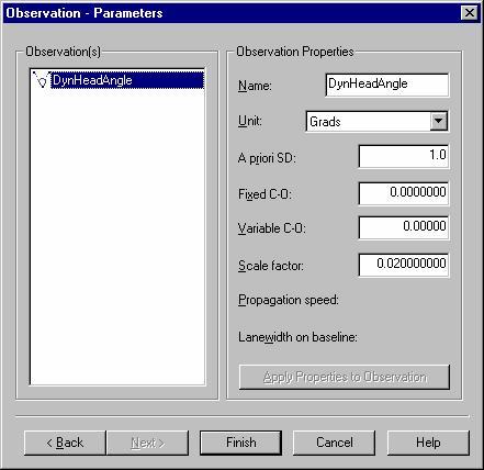
The scale factor is set up for a 20000 pulse per revolution encoder (400 / 20000 = 0.02).
Online
Controller Setup
The motor will start and perform the main routine when the record command is received. Normally the main command will perform a single revolution, each time in an alternating direction. This is subject to the software in the motor drive.
Auto recording
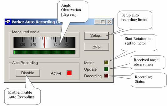
The driver can order the Qinsy Controller to start or stop logging. This option can be enabled or disabled with the Enable/Disable button. Note that disabling auto recording will not stop logging if logging is in progress. The Active Led shows if option is active.
The auto recording works as follows.
When the measured angle falls outside the user defined sector limit then recording is started.
If recording is in progress and the angle falls inside the sector limit then recording will be ended.
If Angle resides within sector for longer then a user defined number of seconds then a 'Start Rotation' command is sent to the motor. The latter will also make sure then when enabling the auto recording option then the motor will be commanded to start after the user defined number of seconds.
The driver will not commandeer the Controller for any used database names. The naming convention is used in the controller according to the user defined session setup settings. It is strongly advised to use a prefix number for the database name.
Main window of driver
If Auto recording is disabled then the driver will issue the 'Start Rotation' command as soon as the user presses the 'Record' button in the Controller. If Auto recording is enabled then nothing is sent in that case.
Note: Auto recording functionality relies on the decoded angle observation. If no angles are decoded then the start/stop logging commands will not be issued.
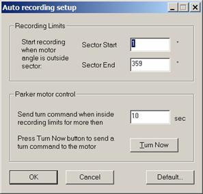
Setup dialog
-
Recording Limits
Define here the start/stop recording sector. If angle falls inside the range then logging will be stopped, if outside then logging is active. -
Parker motor control
The driver uses the timeout after motor 'arrives' in the recording limits sector. It will wait for the timeout to expire before a new 'Start Rotation' command is issued to the motor. -
The 'Turn Now' button can be used to send a 'Start Rotation' command to the motor. Note that the motor will only start turning if communication settings and cable are correct.
These settings need to be entered only once; the settings will be stored in the registry and automatically retrieved when Qinsy is started.
Example of working sequence
-
Motor is idle (usually in position angle 0.0)
-
User Starts Qinsy
-
User enables Auto recording option.
-
After xx seconds the driver will send 'Start Rotation' to motor because angle falls inside recording limits sector.
-
Motor starts turning.
-
Angle changes, falls outside recording limits sector.
-
Driver detects angle outside sector and commands Controller to start recording.
-
Recording is in progress and motor makes the scan.
-
At the end of the turn angles falls inside limits sector again. Driver commands Controller to stop recording.
-
XX seconds after previous step a new 'Start Rotation' command will be send to motor and cycle is repeated.