Optimal Ranging Orion - 23
Description
This driver decodes the solution and field messages of Optimal Ranging's underwater utility surveying product Orion. The driver does not have the capability to command the device. Please use the vendor's tooling to configure the device prior to using it in Qinsy.
Driver Information
Driver | Orion | Interface Type | Serial | Driver Class Type | Terminated |
|---|---|---|---|---|---|
No | Input / Output | Input | Executable | drvQpsTerminated.exe | |
Related Systems |
| ||||
Related Pages | |||||
Database Setup
General
The Orion system does not provide a time stamp with the messages. Therefore, the time of arrival is used as the time stamp for the decoded observation.
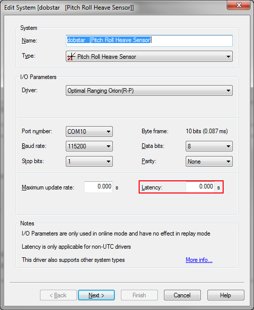
Because the Orion has a fixed delay between the actual observation and the time at which the message arrives in Qinsy, a fixed latency should be entered for each system that uses the Orion driver.
The latency can be entered in the first page of the 'Edit system' dialog. The latency that should be used is 1.386 seconds.

Pitch Roll Heave Sensor
Use "Optimal Ranging Orion (R-P)" as driver. The default settings (apart from the port settings and the latency) are correct.
Gyro Compass
Use "Optimal Ranging Orion" as driver. The default settings (apart from the port settings and the latency) are correct.
This driver will provide the magnetic heading of the Orion.
Multibeam Echosounder
Use "Optimal Ranging Orion" as driver.
Set the proper latency and port settings and set the 'Max beams per ping' field to '2'. Other than that the default values are correct.
USBL system
The USBL system provides the position of utility detection relative to the Orion. The USBL system can be used to display a projection of the utility in the Navigation display and/or the Profile display.
To create such a setup:
Make sure that you have configured an Orion object with at least a gyro system.
Make sure that a Miscellaneous system is added to the system that at least decodes slot "INV_YAW"
Create a new object that represents the utility.
Type: Vessel.
Use a proper shape that mimics the shape of the utility.
Add a gyro system to the 'utility' object.
Use 'System Cloner' for the driver.
Choose the gyro system on the Orion object as the system to clone.
Choose the inverted yaw observation of the miscellaneous system (see step 2) as the offset.
Position the utility object by adding a USBL system to the Orion object:
Use "Optimal Ranging Orion" as driver & set the appropriate port settings
Use the CoG of the Orion as the transducer position
Use the CoG of the utility object as the USBL target
Miscellaneous System
Use "Optimal Ranging Orion" as driver and provide the proper port settings.
All slot ID's as described in the system chapter are available.
Systems
The following systems are decoded by the driver:
Pitch, Roll & Heave
Pitch and roll are decoded from the solution message. There is no heave in the message.
Gyro Compass
Magnetic heading is decoded from the solution message.
Multibeam Echosounder
A multibeam system is decoded from the solution message. This multibeam system consists of two 'beams'. Beam one indicates 'top of utility', beam two 'top of seabed'.
X,Y and Z coordinates of the footprints are calculated from the solution message in the following way:
Beam | X | Y | Z |
|---|---|---|---|
1 | -1.0 * offset * cos(cable yaw) | offset * sin(cable yaw) | depth from reference point |
2 | Altimeter |
USBL
A USBL system is decoded from the solution message. This USBL system gives the position of the detected point in the utility relative to the Orion.
X, Y and Z coordinates are calculated in the same way as beam 1 of the multibeamer system.
Miscellaneous system
All fields that are not decoded by one of the aforementioned systems, are available as a miscellaneous observation:
Value | Slot ID |
|---|---|
Solution ($IISOL) message | |
Solution status | SOLSTAT |
Solution frequency | FREQ |
AC magnetic field | MAGFIELD |
Offset from reference point | OFFSET |
Offset confidence | OFF_CONF |
Depth confidence | DEP_CONF |
Current | CURRENT |
Current confidence | CUR_CONF |
Current phase | CUR_PHASE |
Yaw of cable from E-Pod | CABLEYAW |
Inverted yaw of cable from E-Pod | INV_YAW |
DC magnetic gradient along sensor pair #1 axis | MGRAD1 |
DC magnetic gradient along sensor pair #2 axis | MGRAD2 |
DC magnetic gradient along sensor pair #3 axis | MGRAD3 |
Pressure | PRESSURE |
Magnetic heading | HEADING |
Field ($IIFLD) message | |
Sensor pair | SNSRPAIR |
Frequency | FLD_FREQ |
AC field for sensor 1X, real part | ACFLD1XR |
AC field for sensor 1X, imaginary part | ACFLD1XI |
AC field for sensor 1Y, real part | ACFLD1YR |
AC field for sensor 1Y, imaginary part | ACFLD1YI |
AC field for sensor 1Z, real part | ACFLD1ZR |
AC field for sensor 1Z, imaginary part | ACFLD1ZI |
AC field for sensor 2X, real part | ACFLD2XR |
AC field for sensor 2X, imaginary part | ACFLD2XI |
AC field for sensor 2Y, real part | ACFLD2YR |
AC field for sensor 2Y, imaginary part | ACFLD2YI |
AC field for sensor 2Z, real part | ACFLD2ZR |
AC field for sensor 2Z, imaginary part | ACFLD2ZI |
DC field for sensor 1, real part | DCFLD1R |
DC field for sensor 1, imaginary part | DCFLD1I |
DC field for sensor 2, real part | DCFLD2R |
DC field for sensor 2, imaginary part | DCFLD2I |
