Description
Driver to be used to decode USBL X, Y, Z measurements to a target plus additional measurements such as vessel heading, roll, pitch & warning/error code.
Driver can be used to decode ORE Trackpoint II ASCII Formats and NUWC TCT - TO (=Tracked Object) ASCII Format.
Two versions of the driver are available: a Serial version and a Network version (UDP). If a network driver for the Trackpoint II is required the NUWC TCT - TO driver can be used.
The internal workings of the drivers are the same except for the data reception.
Driver Information
|
Driver |
NUWC TCT-TO
|
Interface Type |
UDP/Serial |
Driver Class Type |
Terminated <LF> |
|---|---|---|---|---|---|
|
No |
Input / Output |
Input |
Executable |
DrvUsblTerminatedUdp.exe ORE_TRACKPOINT
|
|
|
Related Systems |
|
||||
|
Related Pages |
|
||||
Coding Notes
Decoding Notes
If the driver encounters a warning/error code in range 1 to 10 the update is ignored by the driver and therefore also isn't stored in the database.
Currently the following warning/error codes are known to us:
|
Error code |
Description |
|
0 |
No errors detected |
|
1 |
Unusable signal received |
|
2 |
Signal timing error |
|
3 |
Range cannot be determined |
|
4 |
Low quality factor |
|
5 |
Target velocity excessive |
|
6 |
No recent replies |
|
7 |
Minimum range error |
|
8 |
Simultaneous reply error |
|
9 |
Transmitter inoperative |
|
10 |
Travel time less than turn around time |
|
14 |
Maximum slant range exceeded |
|
15 |
Bearing limits exceeded |
|
22 |
Telemetry signal timing error |
|
23 |
Telemetry timing out of range |
|
24 |
Telemetered depth greater than slant range |
|
26 |
No recent telemetry replies |
|
50 |
Target input depth not within normal limits of calculated depth |
|
51 |
Pinger depression angle < 20 deg (including hydrophone offsets) |
|
52 |
Pinger depression angle < 20 deg |
|
53 |
Pinger depression angle 20 - 45. Position approximated |
|
54 |
Target center mode cancelled |
|
55 |
Compass not active |
|
56 |
Transponder or Responder depression angle > 45 deg |
|
57 |
Depth > slant range |
|
59 |
No external key received within wait period. Target was internally keyed |
|
60 |
System ignores phase count depression angle. Using slant range & input depth. |
|
61 |
Calculated horizontal range > slant range |
|
62 |
System performing auto offset function |
|
64 |
Low quality factor |
Note: warning codes do not apply to NUWC-TO format.
NUWC-TO:
The X,Y,Z, values are calculated from horizontal range and bearing (X,Y) and slant range and depression angle (Z).
The timestamp from the message is decoded as observation time (but only if a PPS system is defined in Qinsy Template), the time-of-arrival time stamp is ignored.
UDP Version:
The UDP driver will only decode the formats successfully if a full message arrives per network packet.
If a message arrives scattered over multiple packets then it will not decode.
Qinsy Config
Database Setup
NUWC-TO format
Slot numbers
In order to decode transponder data it is necessary to enter the complete 'Tracked Object Identifier' (as found in the data string from the tracking computer) as slot number in Database Setup.
For instance, if transponder 3, upper transducer, raw data is required then use slot 'AU03'; lower transducer raw data -> 'AL03'.
USBLl system setup
In order to use transponder data for both usbl transducers (lower and upper) you should define two usbl systems: one for the upper transducer, one for the lower transducer.
If the communication parameters (com port number, baudrate etc.) are kept the same then only a single driver (reading from one comport) is started that will support both systems.
Add transponders 'xUxx' to the upper system and 'xLxx' to the lower system.
Choose per usbl system either only raw data (A) or Tracked data(T) transponders since the transducer location differs per data type: for A the range/bearing refers to the transducer array, for T it refers to the submarine reference point.
Note: Units should be set to feet.
Compass Heading
To decode the compass heading field, add a "System" of type "Gyro", select the driver, and define the heading parameters.
To decode all four observations (USBL range/bearing/depth and gyro heading), add both these system types to the Qinsy database and make sure to select the same driver name and the same I/O parameters for both systems (does not apply to NUWC-TO format).
For the Slot Id enter the exact USBL target number.
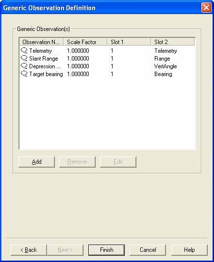
Target bearing, depression angle, slant range and telemetry
To decode the target bearing, depression angle, slant range, telemetry and warning code fields of the NUWC & NUWC-EC formatted string, add a "System" of type "Miscellaneous", select the driver, and define 5 observation with the Slot 2 set using the following table.
In this case the "Slot 1" field is still used to designate the USBL target number for which you want to decode this data (does not apply to NUWC-TO format).
|
Observation |
Slot 1 |
Slot 2 |
|
Target bearing |
<USBL target number> |
Bearing |
|
Depression angle |
<USBL target number> |
VertAngle |
|
Slant range |
<USBL target number> |
Range |
|
Telemetry |
<USBL target number> |
Telemetry |
|
Warning code |
<USBL target number> |
Warning |
Below you will find an example for "target 1":