
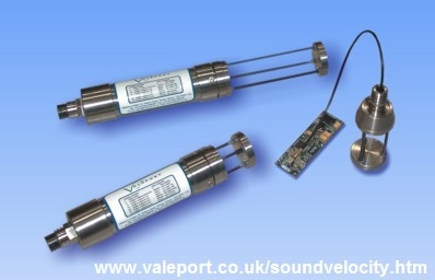
Description
Driver with user-interface to decode the on-line measured sound velocity and pressure from a Valeport miniSVS Sound Velocity Sensor (equipped with the optional pressure sensor) or a Valeport miniSVP Profiling system.
In order to create a sound velocity depth profile, the miniSVS must have been fitted with a pressure sensor. The measured hydrostatic pressure value, decoded as deciBar, is converted automatically by the driver to depth.
For this, the standard ocean depth formula, published by Unesco, is used. The only required input parameter is your approximate latitude, in degrees, of the survey area.
The measured sound velocity is decoded as meters/second, and will be in the range of 1400-1600 m/s.
The miniSVS/miniSVP should be equipped with and connected to a long data/power cable. I.e. that during collection of data for the creation of the depth profile, the user must lower the sensor into the water until the ocean bottom surface is reached.
As soon as a new profile is created, the Controller is informed, and Qinsy may continue using the new sound velocity profile.
Driver Information
|
Driver |
Valeport miniSVS/miniSVP |
Interface Type |
Serial |
Driver class type |
Terminated |
|---|---|---|---|---|---|
|
No |
Input / Output |
Input |
Executable |
DrvQPSTerminatedUI.exe |
|
|
Related Systems |
|
||||
|
Related Pages |
|
||||
Interfacing Notes
The driver is a so-called active driver, this means it receives data and it sends data (commands).
There are two versions of this driver (Serial and Network). The user-interface for both drivers is exactly the same, only the I/O protocol is different.:
-
Serial driver
-
Receiving data from, and sending data to, is done via the same serial COM port, so wiring of the interface must be bi-directional.
If you use the standard supplied serial power/data cable, wiring is already correct
In case you are using your own serial cable, connect the pins using the following diagram:
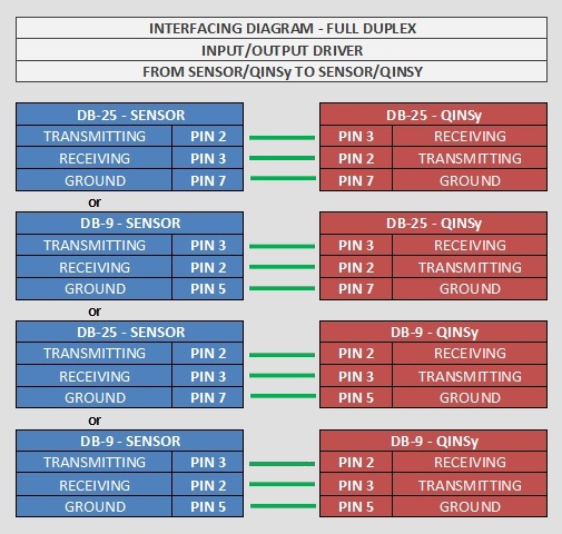
Please refer further to the Valeport Operating Manual for detailed wiring information. -
-
Network driver
-
For the network driver version, receiving data from, and sending data to, is done via the same LAN UDP port.
-
Database Setup
Serial
Notice that the default interfacing settings of the miniSVS are set to 19200, 8, 1, none.
The default settings of the miniSVP are 115200, 8, 1, none.
Please refer to the Valeport Operating manual in case you want to change the baud rate settings.
Leave the maximum update rate at 0.000s. You will be able to change the update (Sampling) rate while on-line, using the driver's dialog.
General
The Valeport miniSVS can be added as two different systems:
-
MiniSVP
If you only need the sound velocity profile, add it as an SVP system. -
MiniSVS
Another option is adding the miniSVS as an Underwater Sensor system, enabling you to get real-time ROV Depth, Pressure, Draft and Sound Velocity from it. The sensor is then configured as a normal Underwater Sensor.
You can choose not to select a slot value for your observations; the correct measurement will be decoded automatically.
In this case, ignore the warning message you get on pressing Next ("No Slot value was entered. Do you wish to proceed anyway?").
Online
The driver has user-interface and should be present in the Windows task bar.
When going on-line for the first time, locate the driver in the task bar, and set the approximate latitude of your survey/work area.
You only have to do this once, unless you go to a different area.
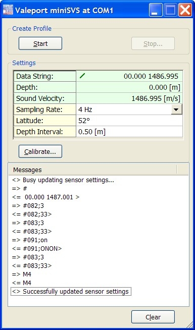
During start-up and initialization of the driver, some required commands are automatically sent to the sensor, in order to get the correct format.
These command settings are also sent when you change the sampling rate.
Notice that all communication messages to and from the sensor are displayed in the Messages list of the driver's dialog.
If all is okay and working well, you should see on every update a spinning icon in the first row, followed by the received raw data string.
The format of the expected raw data string is shown under Format Description
Calibration of the pressure sensor is recommended prior to the start of every depth profile creation.
Just take the miniSVS/miniSVP sensor out of the water, and select the [Calibrate...] button.
After a successful calibration, you should be able to locate the Measured Air Pressure value in the Messages List. Further, the depth reading in the second row should be +/- 0.000 [m].
Now you may start generating a depth profile:
Press the [Start] button, and lower the sensor in the water, until you reach the sea bottom.
As soon as you press Stop and confirm, a profile will be generated. Further, the Controller will be informed that a new Sound Velocity Profile is available.
It depends on the Echosounder Settings in the Controller, whether this new profile is accepted immediately, or whether it needs to be validated prior to accepting.
User-Interface Dialog
Description of the Create Profile action buttons
|
[Start] |
The driver will start collecting data for a new depth profile. After confirmation, the deck-hand must proceed lowering the sensor into the water until the sea bottom is reached. At this point, select the Stop button in order to generate the profile. |
|
[Stop] |
The driver will stop collecting data, after confirmation. A profile will be generated and the Controller is informed. The values of the new profile can be monitored directly in the message list. |
Notice that the Start and Stop action does not send any commands to the sensor. So make sure that the data string is already coming in correctly and the depth and sound velocity values are decoded with reasonable figures.
Description of the settings:
|
Data String |
This field shows the last received data string from the sensor. The spinning icon in front of the data string is updated with every new received string. |
|
Depth |
This field shows the depth in [m], after converting the decoded pressure and latitude, using the standard ocean depth formula. Notice that for shallow water the depth is almost the same as the pressure in decibar.
|
|
Pressure |
Lat 0° |
Lat 30° |
Lat 45° |
Lat 60° |
|---|---|---|---|---|
|
500db |
496.6m |
496.0m |
495.3m |
494.7m |
|
1000db |
992.1m |
990.8m |
989.5m |
988.2m |
|
2000db |
1979.6m |
1976.9m |
1974.3m |
1971.7m |
|
5000db |
4915.0m |
4908.6m |
4902.1m |
4895.6m |
|
10000db |
9725.5m |
9712.7m |
9699.8m |
9687.0m |
|
Sound Velocity |
This field shows the decoded sound velocity value as is, in meters/second. |
|
Sampling Rate |
When changing the sampling (or update) rate, certain commands will be sent to the sensor, in order to tell the sensor how often it should output the data string.
|
|
Latitude |
Enter the approximate latitude of your survey/work area. This value is used as input parameter for the standard ocean depth formula, in order to convert pressure to depth. See also the table above. |
|
Depth Interval |
Depth interval for the profile. If you leave this value to zero, all received samples will be part of the profile. The default 0.5m is recommended to use. |
|
[Calibrate] |
A calibration should be performed prior to every depth profile creation. It actually resets the pressure to zero, so it is important to have the sensor out of the water or just at the water surface (at depth 0).
|
|
[Clear] |
The message list contains a maximum of the last 200 message. Use the Clear button to empty the list. |
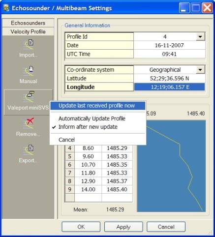
Controller Setup
As soon as a new profile is generated, the Controller is informed.
Select in the Controller the Echosounder Settings from the Settings pull down menu, and locate in the Velocity Profile Settings the Valeport miniSVS system.
Click on the icon, and three options become available:
|
Update last received profile now |
Select this option to import the last generated profile. This option is recommended because prior to pressing the OK or Apply button, the user may validate the profile. |
|
Automatically Update Profile |
Enable this option in order to accept the new profile immediately, without any validation. All other Qinsy processes are also informed automatically.
|
|
Inform after new update |
When this option is enabled, a message box will pop up in front of the Controller's view, informing the user about the new profile. |
Additional Information
When the driver stops collecting data to generate a profile, two files will be created in the project LogFiles folder, both with extension *.SVP.
The first one is named "<System Name>.SVP".
The second one is named "<System Name> JDxxx HHMMSS.SVP", where <System Name> is the name of the system, as entered in Database Setup, xxx the julian day of the year and HHMMSS the UTC time.
The first file will be overwritten when new profile data is collected, so that this file will always contain the latest up-to-date profile.
A user can always import a previously generated profile by using the file Import option: use icon and select a previously created *.SVP file.
File type must be "Comma Separated (depth,speed,temp,sal,cond,dens,pressure)".