
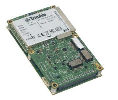
Driver to decode data from Trimble products using proprietary format GSOF (General Survey Output Format).
This includes most additional GSOF messages from Applanix AP+ units.
The following data can be decoded and stored from the different GSOF message types:
-
Positions
-
Headings
-
Motion (Roll, Pitch and Heave)
-
UTC Time
-
Angle and Speed vectors
-
Velocities, Accelerations and Rotations
-
Metadata (Status flags, Quality indicators, etc.)
Driver Information
Click to expand details...
System Interfacing
Click to expand interfacing details...
Message Types
Note that this driver will only decode and use data from the following message types:
-
Standard GSOF message types: 1, 2, 8, 12, 16, 27, 37
-
AP+ specific message types: 49, 50, 63, 64, 65, 66, 67, 68
It does also depends on the template database system setup whether one of the enabled message types are used or not.
Use the manufacturer's GUI to enable the specific output messages needed and its update rate:
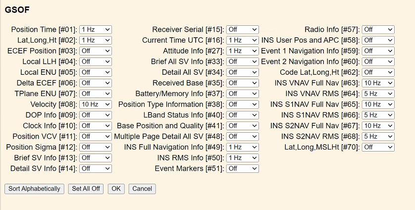
GUI Example
There is no use to enable any of the other message types for this driver, but feel free to contact QPS if you do need decoded information from one of the unsupported types.
Timing
-
When your template setup has a valid Time Synchronization System (PPS) defined then the driver will time-stamp the observations using the decoded time from standard GSOF message type 16 (Current Time UTC).
Therefore make sure to enable message type 16:
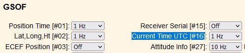
Important is to set the update rate to 1 Hz
-
When your template setup does not have a valid Time Synchronization System (PPS) defined and/or standard GSOF message type 16 hasn't been enabled then the time-of-arrival (at the I/O port) will be used for time-stamping the decoded observations.
Database Setup
It is important to use the same interfacing settings for all 'Trimble/Applanix GSOF' systems in your template setup.
Click here to expand setup details...
Position Navigation System
Add a Position Navigation System to your template setup and select driver:
"Trimble/Applanix GSOF (Position)" when using the serial I/O interface, or
"Network (UDP/TCP) - Trimble/Applanix GSOF (Position)" when using the network interface.
The latitude, longitude and height observation can be decoded from:
-
Standard GSOF message type 2 (LLH)
-
One of the AP+ specific message types:
-
49 (Reference),
-
63 (Vessel),
-
65 (Sensor 1) or
-
67 (Sensor 2)
which needs to be selected on the second wizard page.
-
First Wizard Page
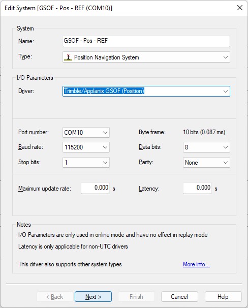
Example serial interface
Second Wizard Page
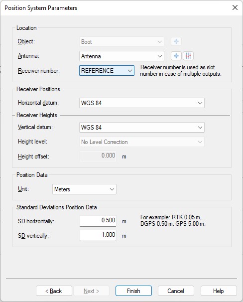
-
Location
Select the correct antenna location that represents the position of the selected receiver number. -
Receiver number
Important setting to select from which message the latitude, longitude and height observations and qualities (root mean square) should be decoded:-
REFERENCE
Observations and qualities will be decoded from AP+ specific message type 49 and 50 (reference frame navigation solution and rms). -
VESSEL
Observations and qualities will be decoded from AP+ specific message type 63 and 64 (vessel frame navigation solution and rms). -
SENSOR1
Observations and qualities will be decoded from AP+ specific message type 65 and 66 (sensor 1 frame navigation solution and rms). -
SENSOR2
Observations and qualities will be decoded from AP+ specific message type 67 and 68 (sensor 2 frame navigation solution and rms). -
02
Observations and qualities will be decoded from general GSOF message type 2 and 12 (position llh and sigma).
-
-
Horizontal / Vertical Datum
Select the correct horizontal datum that is applicable for the latitude and longitude fields.
Select the correct vertical datum that is applicable for the accompanying height field.
Both datums are always assumed to be on WGS84
The update rate of GSOF messages are configurable inside the manufacturer's gui and can be higher than 10 Hz for most messages.
For accurate positioning inside Qinsy a higher update rate is not necessary for the position specific messages and may even degrade performance, slowing down computations, increasing recorded database file sizes, etc.
By default the driver will limit the update rate of the positions to 10 Hz.
An advanced user may change this default limitation of max 10 Hz incoming positions by altering the value of the following registry key while offline:
Serial driver:
HKEY_CURRENT_USER\Software\QPS\QINSy\8.0\Drivers\DrvQPSCounted\Settings\GSOF MaxPosUpdateRate [Hz]
Network driver:
HKEY_CURRENT_USER\Software\QPS\QINSy\8.0\Drivers\DrvQPSCountedUDP\Settings\GSOF MaxPosUpdateRate [Hz]
HKEY_CURRENT_USER\Software\QPS\QINSy\8.0\Drivers\DrvQPSCountedTCP\Settings\GSOF MaxPosUpdateRate [Hz]
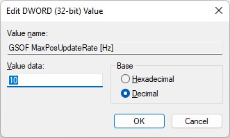
Entering a value of 0 (zero) means all incoming positions will be decoded.
The default limitation only counts for positions, all other observations (roll, pitch, heading, velocities, etc) are decoded without any restrictions.
Gyro Compass System
Add a Gyro Compass System to your template setup and select driver:
"Trimble/Applanix GSOF (Heading)" when using the serial I/O interface, or
"Network (UDP/TCP) - Trimble/Applanix GSOF (Heading)" when using the network interface.
The heading observation can be decoded from
-
Standard GSOF message type 8 (Velocity), type 27 (Attitude)
-
One of the AP+ specific message types:
-
49 (Reference),
-
63 (Vessel),
-
65 (Sensor 1) or
-
67 (Sensor 2).
This source needs to be selected on the second wizard page.
-
First Wizard Page
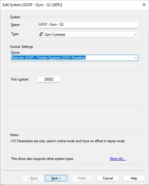
Example UDP network interface
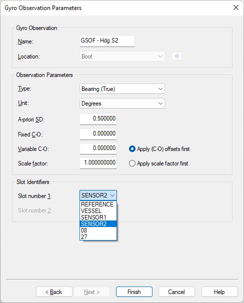
Second Wizard Page
-
Unit must be 'Degrees'.
(Note that for some message types the heading is published using radians but here you always need to select degrees) -
Slot number 1
Important setting to select from which message the heading observation should be decoded:-
REFERENCE
Heading and quality (rms) will be decoded from AP+ specific message type 49 and 50 (reference frame navigation solution and rms). -
VESSEL
Heading and quality (rms) will be decoded from AP+ specific message type 63 and 64 (vessel frame navigation solution and rms). -
SENSOR1
Heading and quality (rms) will be decoded from AP+ specific message type 65 and 66 (sensor 1 frame navigation solution and rms). -
SENSOR2
Heading and quality (rms) will be decoded from AP+ specific message type 67 and 68 (sensor 2 frame navigation solution and rms). -
08
Heading and quality (velocity flag) will be decoded from general GSOF message type 8 (Velocity).
The heading computation for the Velocity (type 8) message is derived from consecutive positions. -
27
Heading (Yaw) and quality (variance) will be decoded from general GSOF message type 27 (Attitude)
The heading computation for the Attitude (type 27) message is computed from the moving baseline vector and requires a two-antenna system.
-
Pitch Roll Heave Sensor
Add a Pitch Roll Heave Sensor to your template setup and select driver:
"Trimble/Applanix GSOF (Roll Pitch Heave)" when using the serial I/O interface, or
"Network (UDP/TCP) - Trimble/Applanix GSOF (Roll Pitch Heave)" when using the network interface.
The motion observations can be decoded from:
-
Standard GSOF message type 27 (Attitude)
-
One of the AP+ specific message types:
-
49 (Reference),
-
63 (Vessel),
-
65 (Sensor 1) or
-
67 (Sensor 2).
This source needs to be selected on the second wizard page.
-
Note that a heave observation is not available in standard GSOF message 27 (Attitude) or AP+ specific message 49 (Reference Frame).
A heave value is only available in AP+ specific message type 63 (Vessel), 65 (Sensor 1) or 67 (Sensor 2).
First Wizard Page
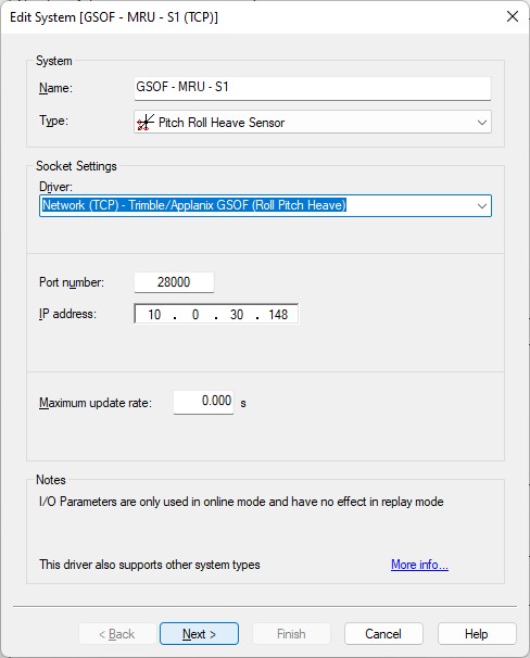
Example TCP network interface
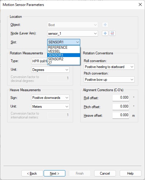
Second Wizard Page
-
Select the correct Node location.
This will be the node location that represent the frame for the selected Slot. -
Slot
Important setting to select from which message the motion observations and qualities (rms or variance) should be decoded:-
REFERENCE
Roll and pitch will be decoded from AP+ specific message type 49 and 50 (reference frame navigation solution and rms). -
VESSEL
Roll, pitch and heave will be decoded from AP+ specific message type 63 and 64 (vessel frame navigation solution and rms). -
SENSOR1
Roll, pitch and heave will be decoded from AP+ specific message type 65 and 66 (sensor 1 frame navigation solution and rms). -
SENSOR2
Roll, pitch and heave will be decoded from AP+ specific message type 67 and 68 (sensor 2 frame navigation solution and rms). -
27
Roll and pitch will be decoded from general GSOF message type 27 (attitude).
-
-
Sign Conventions
Make sure to use to following (Applanix) sign conventions:-
Roll: Positive heeling to starboard
-
Pitch: Positive bow up
-
Heave: Positive downwards
-
Rotation Measurement Type: HPR (roll first)
-
Third Wizard Page
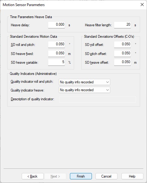
-
You may leave all parameters at their defaults
Time Synchronization System
Add a Time Synchronization System to your template setup and select driver:
"Trimble/Applanix GSOF (Current Time #16)" when using the serial I/O interface, or
"Network (UDP/TCP) - Trimble/Applanix GSOF (Current Time #16)" when using the network interface.
Time will be decoded from:
-
Standard GSOF message type 16 (Current Time UTC)
First Wizard Page
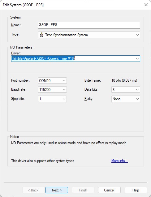
Example serial interface
Second Wizard Page
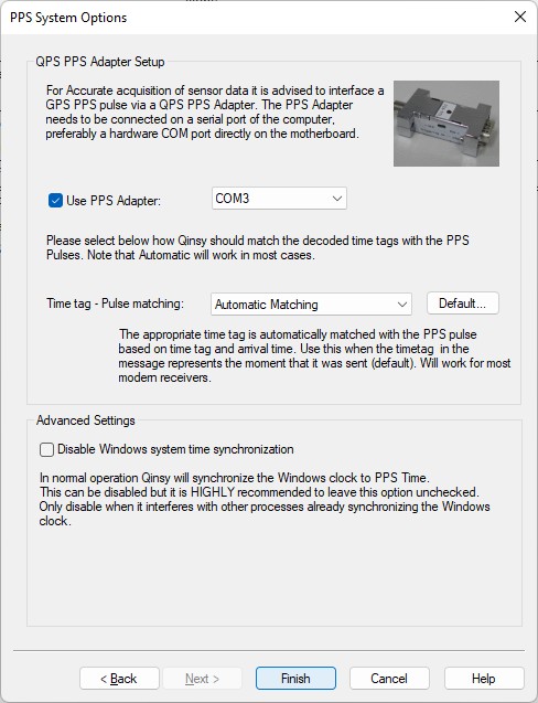
Note that the Time tag (GSOF message type 16) is always coming shortly after the PPS pulse (5-20 ms), therefore you may leave the Time tag - Pulse matching set to 'Automatic Matching'.
Notes
-
Make sure to enable message type 16; the current UTC time will be decoded from this message:

Important is to set the update rate to 1 Hz. -
This type 16 message contains a value for the GPS week number, the GPS week seconds and a GPS to UTC offset value (aka leap-second).
-
The message will also contain two status indicators: the first one indicates if the time is valid and the second one indicates if the reported GPS to UTC offset is valid.
-
Qinsy will only accept and use the decoded time when the first status indicator is okay.
-
The driver converts the GPS time to UTC time and for this it will use the GPS to UTC offset but only when the second indicator is okay.
If this second status indicator is not okay then the UTC to GPS correction from the template database setup will be used. -
Use a Time Synchronization Display to monitor this system while being online.
For easy monitoring you can see the decoded values formatted as a text string in the status column of this display.
Speed Log
Add a Speed Log to your template setup and select driver:
"Trimble/Applanix GSOF (Angle & Speed)" when using the serial I/O interface, or
"Network (UDP/TCP) - Trimble/Applanix GSOF (Angle & Speed)" when using the network interface.
Speed log observations will be decoded from:
-
standard GSOF message type 8 (Velocity)
-
one of the AP+ specific message types (49, 63, 65, 67)
These observations can be used to enhance the results of the kalman filter in the Qinsy computation setup
First Wizard Page
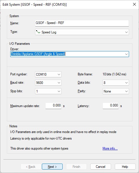
Example serial interface
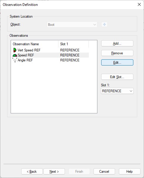
Second Wizard Page
-
Add the required observation types that you want and select for each one the location that represent the frame for the selected Slot 1.
Note that from the listed observation types only the Angle, Speed and Vertical Speed types are supported, the Bearing (True) type observation is not supported.
You may change the default name for each observation as long as it doesn't exceed 16 characters.
-
Important is to select for each observation the Slot 1 Id which defines from which GSOF message the observations will be decoded:
-
REFERENCE
Total Speed, Down Velocity and Track Angle and qualities (rms) will be decoded from AP+ specific message type 49 and 50 (reference frame navigation solution and rms). -
VESSEL
Total Speed, Down Velocity and Track Angle and qualities (rms) will be decoded from AP+ specific message type 63 and 64 (vessel frame navigation solution and rms). -
SENSOR1
Total Speed, Down Velocity and Track Angle and qualities (rms) will be decoded from AP+ specific message type 65 and 66 (sensor 1 frame navigation solution and rms). -
SENSOR2
Total Speed, Down Velocity and Track Angle and qualities (rms) will be decoded from AP+ specific message type 67 and 68 (sensor 2 frame navigation solution and rms). -
08
Horizontal speed and vertical velocity and quality (velocity flag) will be decoded from general GSOF message type 8 (Velocity).
This message does not contain a (relative) track angle, only speed.
-
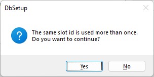
When continuing to the next wizard page just select [ Yes ] when this message-box pops up.
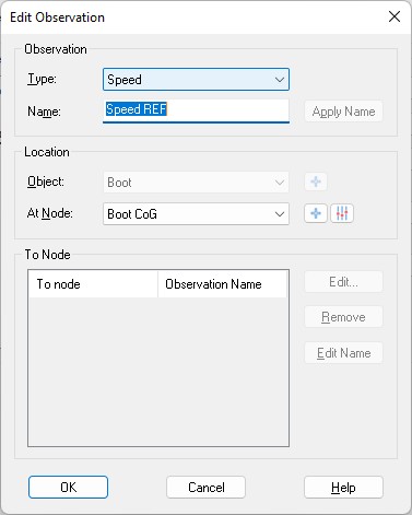
Third Wizard Page
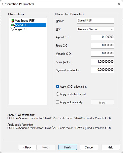
-
On this last wizard setup page you can also change the default name of each observation (as long as it doesn't exceed 16 characters). You may leave all parameters at their defaults.
-
Speed units must be 'Meters / Second'
-
Angle unit must be 'Degrees'
Acceleration Velocity Sensor
Add an Acceleration Velocity Sensor to your template setup and select driver:
"Trimble/Applanix GSOF (Velo, Acc, RoT)" when using the serial I/O interface, or
"Network (UDP/TCP) - Trimble/Applanix GSOF (Velo, Acc, RoT)" when using the network interface.
Velocity, acceleration and rotation observations will be decoded from:
-
one of the AP+ specific message types (49, 63, 65, 67).
First Wizard Page
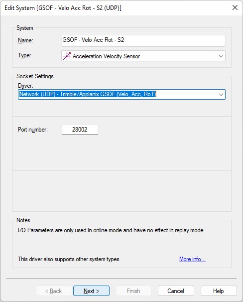
Example of UDP network interface
Second Wizard Page
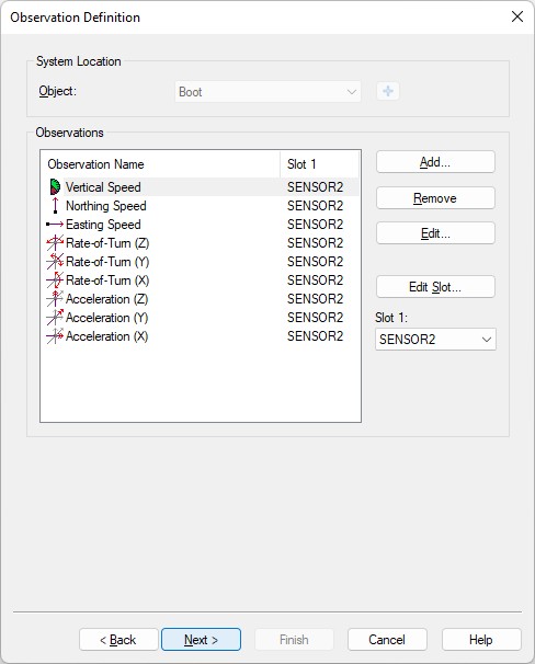
-
Add the required observation types that you want and select for each one the location that represent the frame for the selected Slot 1.
You may change the default name for each observation as long as it doesn't exceed 16 characters.
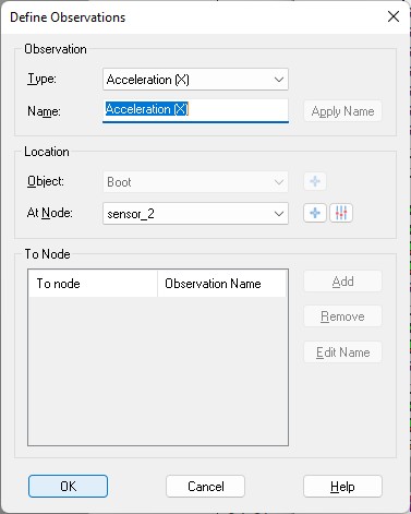
Note that from the listed observation types the types Velocity (X/Y/Z) are not supported so adding these three has no use.
-
Important is to select for each observation the Slot 1 Id which defines from which GSOF message the observations will be decoded:
-
REFERENCE
Observations and qualities will be decoded from AP+ specific message type 49 and 50 (reference frame navigation solution and rms). -
VESSEL
Observations and qualities will be decoded from AP+ specific message type 63 and 64 (vessel frame navigation solution and rms). -
SENSOR1
Observations and qualities will be decoded from AP+ specific message type 65 and 66 (sensor 1 frame navigation solution and rms). -
SENSOR2
Observations and qualities will be decoded from AP+ specific message type 67 and 68 (sensor 2 frame navigation solution and rms).
-
When continuing to the next wizard page please select [Yes] when this message-box pops up.
Third Wizard Page
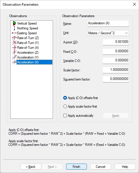
-
On this last wizard setup page you can also change the default name of each observation (as long as it doesn't exceed 16 characters). You may leave all parameters at their defaults.
-
Speed units must be 'Meters / Second'
-
Acceleration units must be 'Meters / Second^2'
-
Rate-of-Turn units must be 'Degrees / Second'
Notes
Adding velocity, acceleration and rotation observations can be useful for analyzing purposes e.g. by monitoring their values in real-time using an Observation Physics Display or graphically using a Timeplot Display.
However these type of observations will not be used by Qinsy to enhance the computation results.
If you need to enhance the result from a possible kalman filter in your computation setup then you should use the angle and speed observations from the Speed Log system setup.
Miscellaneous System
Add a Miscellaneous System to your template setup and select driver:
"Trimble/Applanix GSOF (Metadata)" when using the serial I/O interface, or
"Network (UDP/TCP) - Trimble/Applanix GSOF (Metadata)" when using the network interface.
Generic observations will be decoded from:
-
the header of any AP+ specific message type
-
and/or from standard GSOF message type 1 or 37.
First Wizard Page
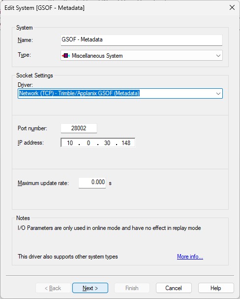
Example of TCP network interface
Second Wizard Page
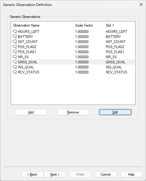
-
Here you can add up to nine generic observations that you may want to monitor.
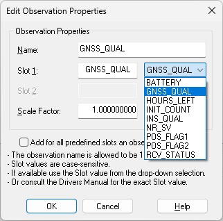
Each generic observation needs a unique Slot Id so the driver knows which field to decode.
It is highly recommended to use the drop-down selection for the correct Slot Id:
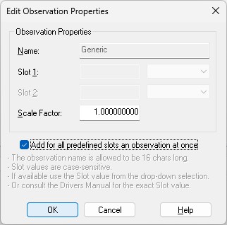
More convenient may be to use the checkbox to add all observations at once.
Of course you can change the default name for each observation as long as it doesn't exceed 16 characters.
Find below a table with all possible Slot IDs:
|
Slot 1 ID |
Observation |
GSOF Message |
|---|---|---|
|
BATTERY |
Remaining battery capacity in percentage |
37 (Battery/Memory info) |
|
GNSS_QUAL |
GNSS Quality Indicator: 0: Fix Not Available
|
From any AP+ specific message header |
|
HOURS_LEFT |
Estimated remaining data logging time in hours |
37 (Battery/Memory info) |
|
INIT_COUNT |
Initialization counter (Increments with each initialization, modulo 256) |
1 |
|
INS_QUAL |
INS Quality indicator: 0: GPS Only
|
From any AP+ specific message header |
|
NR_SV |
Nr of satellites used to determine the position |
1 (Position Time) |
|
POS_FLAG1 |
Flag representing first set of position attribute values: Bit 0: New position (0: No, 1: Yes)
|
1 (Position Time) |
|
POS_FLAG2 |
Flag representing second set of position attribute values: Bit 0: Differential position (0: Differential position is an autonomous or a WAAS solution, 1: Position is a differential solution)
|
1 (Position Time) |
|
RCV_STATUS |
Flag representing Receiver Status Code: Bit 0: Reserved
|
From any General Packet Header (GENOUT) |
Note that the Slot ID is case-sensitive.
Third Wizard Page
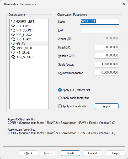
-
Here you can also change the default name of each observation as long as it doesn't exceed 16 characters.
-
You may leave all parameters at their defaults.
Online
The driver has no user-interface so you need to set up several displays to see if data is received, decoded and what the computed results are.
Click here for some examples of useful displays to use with your project...
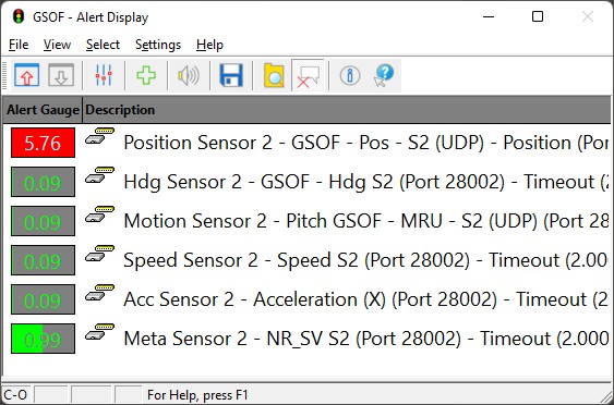
Alert Display
Always useful as a starter to see if data is coming in at the I/O port or not.
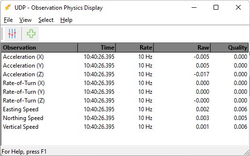
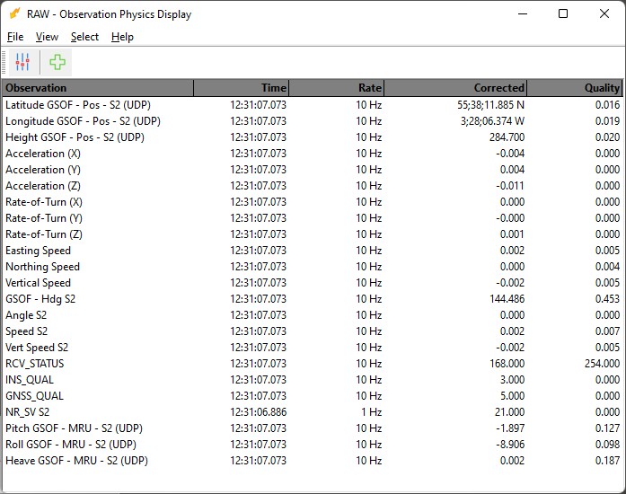
Observation Physics Display
An observation physics display is useful to see if data is coming in, at what update rate and how the values are decoded.
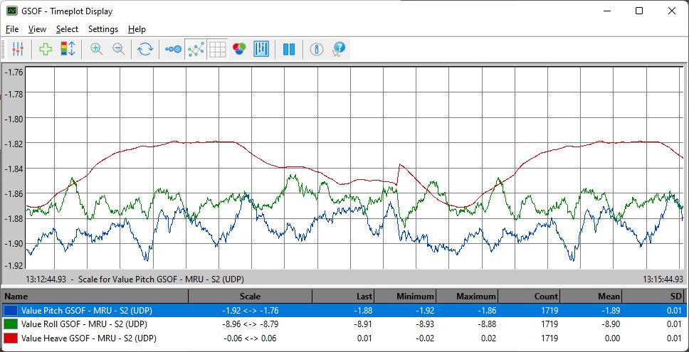
Timeplot Display
A timeplot display is useful to monitor the observations graphically in time with min/max/mean statistics.
Generic Display
A generic display is particular useful to show the meaning of the several status indicators from the meta data observations (GNSS Quality, INS Quality, Receiver Status, Nr of SV's)
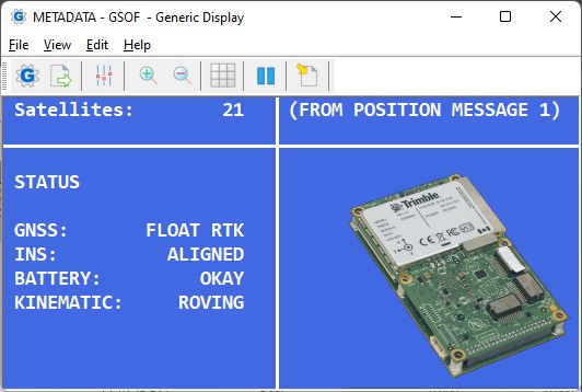
You may use the attached GSOF.xml file as example for getting all the information from the meta data observations .
Copy the layout (Use right-mouse 'Save Link As...') to your current Project's Settings\Display folder and open it using a new Generic Display.
Please note that Save as will not work when you are viewing this document offline through the Qinsy Console; it is only accessible via the QPS website.
After downloading you only need to select the correct miscellaneous system and generic observation as defined in your template setup:
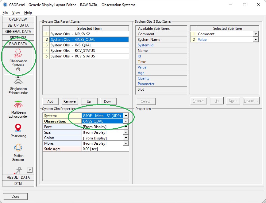
The background picture in this generic display example is not embedded but feel free to browse for your own one 😉
Time Synchronization Display
A time synchronization display is mandatory to verify the accurate timing of all observations using the current UTC time from the unit.
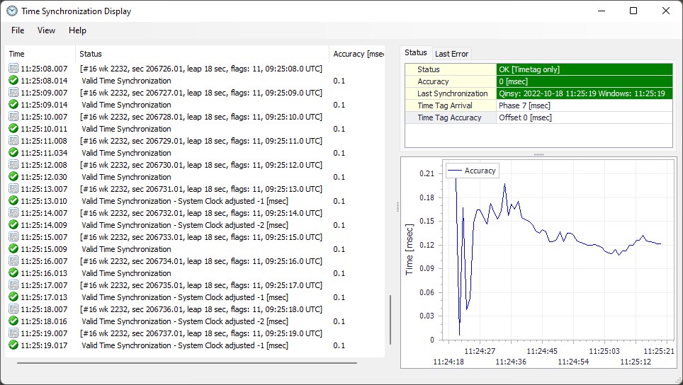
The display will be automatically present when you have added a Time Synchronization System (aka PPS) to your template setup
For this you should have enabled standard GSOF message type 16 (Current Time UTC) with an update rate set to 1 Hz, as explained in the System Interfacing paragraph:

The binary message type 16 contains the GPS week number, the GPS week seconds and a GPS to UTC offset value (aka leap-second).
The values will be decoded by the driver and for easy monitoring also formatted as a text string in the status column of the Time Synchronization display:
[#16 wk nnnn, sec ssssss.ss, leap nn sec, flags nn, hh:mm:ss.s UTC]
In the examples above you'll see for the flags value: '11': the first 1 means that the time is valid and therefore accepted by the driver and the second 1 means that the UTC offset value (leap 18) is valid and therefore also accepted by the driver in order to convert GPS time to UTC.