
Description
Driver for Simrad HiPAP (High Performance Acoustic Positioning) NMEA Format and to be used to decode USBL X, Y and Z data, relative between HiPAP Transducer and Transponder.
The driver supports multiple transducers.
Driver Information
Coding Notes
Decoding Notes
|
SIMRAD_HPR400_NMEA |
NMEA Mode |
|
PPS |
Instead of using I/O time, use time from datastring (Hipap is PPS (Time Synchronization System) synchronized) |
|
NOCS |
Ignore Checksum (only for NMEA messages) |
Qinsy Config
System Configuration
On this page:
Output to Qinsy
-
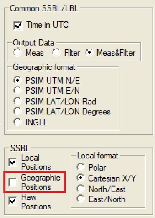
SSBL
-
Local Positions
-
Local Format
-
Cartesian X/Y
-
-
Disable Geographic Positions
Geographic Positions should be disabled, otherwise UTM coördinates will be decoded as coordinates relative to the "Reference Node" (usually the USBL head).
Timing on the HiPAP system
It is advised to use PPS and Time Message on your HiPAP system when using your HiPAP for survey operations to prevent timing issues. To be able to use the PPS Time Synchronization pulse you need to have a special PPS device installed on your HiPAP system.
Some settings of the timing settings your HiPAP:
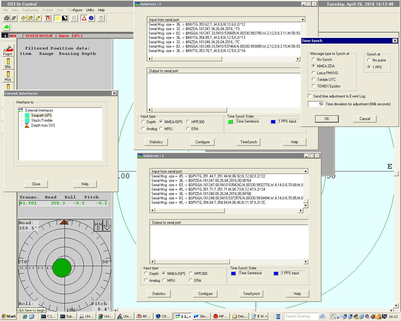
If you have the PPS and Time Message (ZDA) interfaced to your HiPAP system you will be able to use the following HiPAP drivers in Qinsy:
-
Simrad HiPAP (NMEA $PSIMSSR Format) (with UTC)
-
Simrad HiPAP Raw (NMEA $PSIMSSR Format) (with UTC)
Testing
How to change the HiPAP to Simulation Mode:
-
Password: 1997 (Date when APOS was created/released).
-
Add beacon B48. This will automatically generate and simulated beacon output.
Database Setup
USBL System
In order to decode USBL XYZ data, relative between HiPAP Transducer and Transponder, add a USBL System to your template database setup, and select driver "Simrad HiPAP (NMEA $PSIMSSB Format)".
Note: the Coordinate system on the APOS (Simrad unit) must be set to Cartesian or Polar.
-
USBL Parameters
-
Location settings
-
Transducer - Physical Location of the Transducer relative the used CoG in Qinsy.
-
Used within USBL Calibration utility in Qinsy.
-
-
Reference Node - Location for which the USBL is outputting the Beacon results. With Dual Heads a common location like the CoG is used by both heads.
-
Always needed.
-
-
-
USBL XYZ data
-
The HiPAP will output motion corrected beacon offsets (motion sensor interfaced to the HiPAP) relative to selected Reference Node and aligned to the common vessel frame.
-
Make sure you interface the motion sensor used by the HiPAP to Qinsy and used it when performing a Calibration.
-
-
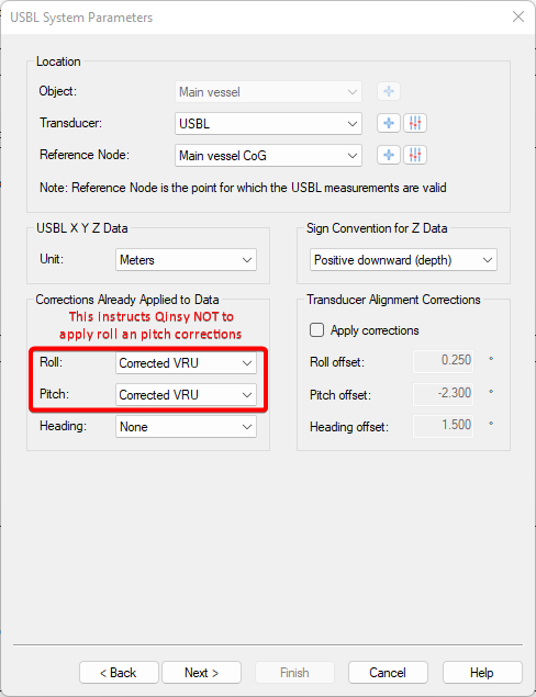
Transducer Alignment Corrections
-
When performing a USBL calibration with APOS, do record the data in Qinsy and perform a USBL calibration with the Qinsy USBL Calibration Utility and check if the results match.
-
Enter the results and un-tick the box: 'Apply corrections', then they will not be reapplied in Qinsy.
-
See FQI-217 for Graphical User Interface (GUI) improvements and click on VOTE if you think its a good improvement.
-
-
-
-
USBL Targets
Slot numbers depend on the used HiPAP transponder or responder. E.g beacon 12 has slot number B12.
The predefined slot-numbers may be changed while working on-line: Select the USBL system in the Controller's Computation Setup, and change the USBL Target Slot Field.
In case of a multiple transducer setup the slot number can be preceded by the transducer number (e.g. 1B12 or 2B47). The driver will then combine the position and sensor messages.
TIP
The transponder code sent with the PSIMSSB USBL message is automatically derived from the name of the chosen node, using its three first letters.
PSIMSSB format:
$PSIMSSB,hhmmss,Btp,qqq,errcode,c,o,f,x.xx,y.yy,z.zz,a.aa,i,,*cc
Where Btp is transponder code
If for example the position is calculated in a node called "SROV USBL CoG", the string sent out would be:
$PSIMSSB,175001.67,SRO,A,,C,H,M,9.93,-2.25,10.74,0.29,T,0.004778,*7A
where "SRO" is automatically taken from "SROV USBL CoG".
Unfortunately the Sprint system will totally reject this position, it needs to be of the format "BXX".
The workaround for this is to change the name of the node to, for example, "B01 SROV USBL CoG".
ARPA System - Shows all beacons in the Navigation Display
-
In order to show all received transponder positions as targets in the Navigation Display, add an ARPA System to your template and select driver "Simrad HiPAP (NMEA $PSIMSSB Format)".
In the Navigation Display under the Target layer the targets can be shown and the labels enabled. This can be very useful for monitoring the performance of the USBL.
-
Note: displayed beacons are never corrected for Transducer Alignment Correction set in the USBL System setup.
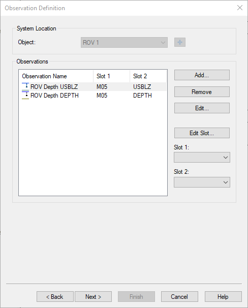
Underwater Sensor
Two depth values can be decoded from the string: USBL Z and Depth from the 'additional info' field. The latter is an optional field that will only be available if the unit is set up to output depth.
The Underwater System needs two slot ID's to determine which Depth to decode:
-
Slot one should contain the beacon ID
-
Slot two should be set to "USBLZ" to decode the Z value, or "DEPTH" to decide depth from the 'additional info' field.
Gyro System
Two heading values can be decoded:
-
The heading as read from the external VRU. This is part of the $PSIMSNS string.
-
The compass heading from the 'additional info' field of the $PSIMSSB string.
In order to decode the heading from the $PSIMSNS string, leave the slot ID field empty.
You will get a warning about an empty slot ID, but you can ignore that.
In order to decode the compass heading from the 'additional info' field of the $PSIMSSB string, set the slot ID to the beacon ID.
Pitch Roll Heave System
This system decodes the optional inclinometer data from the 'additional info' field of the $PSIMSSB string.
Note that this data will only be available if the system is setup to output inclinometer data for the specific beacon.
The system will decode 'X inclination' as roll and 'Y inclination' as pitch. Use the beacon ID as the slot ID.
Position Navigation System
-
In order to decode USBL XYZ data as absolute positions of the HiPAP Transponder, add a Position Navigation System to your template database setup and select driver "Simrad HiPAP (NMEA $PSIMSSB Format)".
Notice that the Coordinate system on the APOS (Simrad unit) must be set to Radians. -
On the second wizard page the Receiver number must be the HiPAP transponder beacon code, but enter only a numerical value. E.g. you should enter for beacon "B09" the number 9. This receiver number (Beacon id) can not be changed while on-line.
Select for Horizontal Datum the same as the APOS presentation datum. Select for Vertical Datum your mean sea level datum. You may perhaps enter a height offset, e.g. -3.0, if the transducer is 3m below the vessel's reference node. -
Note: this "absolute position" approach is sufficient for a horizontal indication of the transponder beacon, but the vertical component is not as accurate as when being positioned using relative XYZ data.
Because the object of the defined Position Navigation System is not connected to the USBL transducer, it does not know the reference of the 'depth' data (Z-component).
Additional Information
Cable lay environment
Kongsberg has recently been investigating the possibilities to allow for variable draft input into APOS from a vessel mounted draft sensor(s).
This always had as a consequence that there is a serious mismatch in Z between the HiPAP transponder/responder depth values in APOS, shown relative to CoG (this is how they are output to Qinsy) compared to the vessel antenna visualised Z values in APOS (geoidal height of the antenna), the Digiquartz transponder measurements on seafloor/quadrant from APOS and the Digiquartz FF ROV measurements from APOS.