
Description
Driver that can be used to interface various models of Septentrio GPS receivers or OEM boards via the SBF (Septentrio Binary Format) binary protocol. For example the models AsteRx2, AsteRx3, PolaRx3, PolaRx4 support this protocol.
The driver interfaces through the network (TCP/IP), through the serial port, or via USB. The Septentrio board acts as a data server. The driver connects to this server, receives its connection identification (e.g. IP11,COM3, USB1) and free stream id (1-10), and requests which packets it would like to receive. See below for the message that is used.
This driver supports beside position and time tag (for Time Synchronization) optionally heading and pitch/roll but obviously only if the GPS receiver supports it and uses multiple antennas.
Older Models PolaRx2
Different drivers are available for the older models PolaRx2. These drivers do not support some of the newer SBF messages and they also require a different request message.
The default Ethernet (network) port is 28784.
The Driver will by default actively request for data. This means that the communication with the receiver needs to be two-way. Some Serial com ports on the receiver are only one-way so they should not be used. Refer to the manual of the receiver to find out which com ports are two-way. The exception is when using the passive driver this only decodes incoming messages.
Driver Information
Decoding Notes
Base-station, -link and BaseVectorGeod(SBF v2) information are not decoded.
The Time Synchronization Timetag is decoded from the ReceiverTime Block.
The format of the Timetag message is created in the driver and has the following format:
SBF Time WNC <GPS weeknumber> TOW <GPS TimeofWeek in msec> DD-MM-YY HH:MM:SS
The date and time fields at the end are in UTC.
Solution mode
The solution mode is decoded from the parameter named 'Mode'.
|
Position Mode |
Solution Mode |
|---|---|
|
0 |
No PVT available |
|
1 |
Stand-Alone PVT |
|
2 |
Differential PVT |
|
3 |
Fixed location |
|
4 |
RTK with fixed ambiguities |
|
5 |
RTK with float ambiguities |
|
6 |
SBAS aided PVT |
|
7 |
moving-base RTK with fixed ambiguities |
|
8 |
moving-base RTK with float ambiguities |
|
9 |
Precise Point Positioning (PPP) with fixed ambiguities |
|
10 |
Precise Point Positioning (PPP) with float ambiguities |
Standard Deviation
This driver will decode the provided variance for Latitude, Longitude, Height, Heading, Pitch, and Roll from the respective data blocks PosCovGeodetic for position and AttCovEuler for heading and motion.
The decoded variance if valid is converted to a standard deviation of 1σ and stored inside the Quality Indicator field.
Interfacing Notes
The Cable wiring diagrams can be found in the User Manual. Note that the serial cable should be two-way because the driver will actively request for data.
If for some reason the driver fails to connect over a serial/USB connection then you can test the connection: open the used port with a Terminal program like the Qinsy I/O tester and send a couple of CR/LF's to it by pressing Enter. The driver should react with the connection Identification and a prompt character, e.g. USB1> or COM3>.
If the receiver has been switched off and on then it is possible that the communication does not start. In that case it is possible to use the option Reset System I/O from the Reset menu in the Controller. This will send the commands to enable messages to the receiver.
Multiple Qinsy's can connect to the same receiver. If Qinsy has a connection with the receiver you will notice a data stream connection
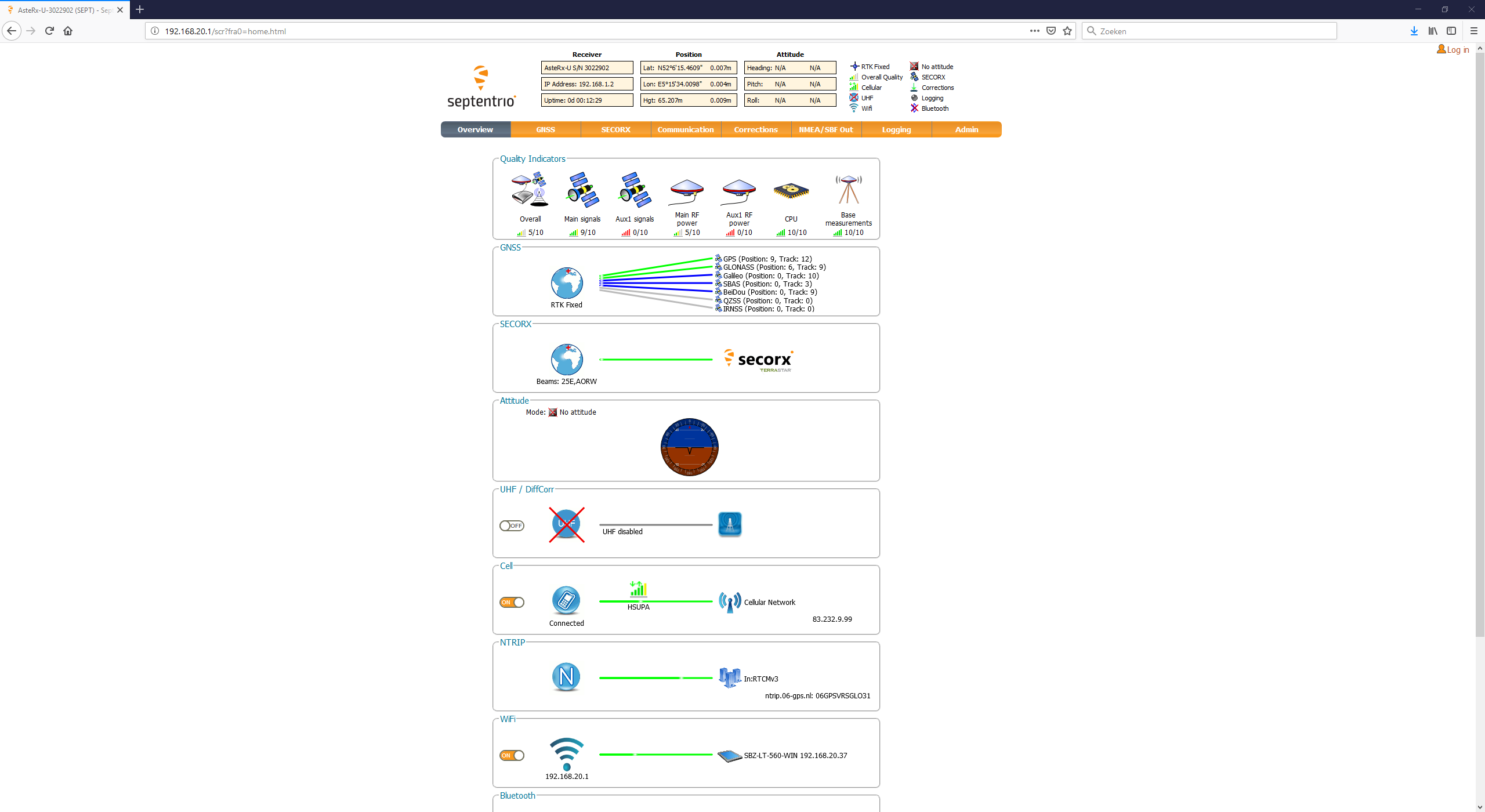
It is possible make a WIFI connection with the receiver via a webinterface.
The default IP-address is 192.168.20.1
System Configuration
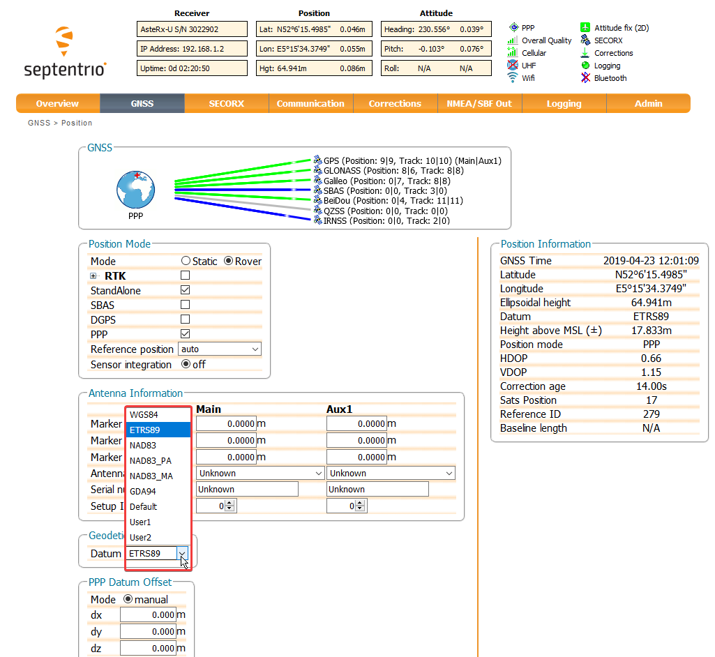
Set output datum
GNSS → Position
-
WGS '84
-
ETRS '89
-
NAD '83
-
NAD '83_PA
-
NAD '83_MA
-
GDA '94
-
Default → no transformation is done
-
User 1 → Custom transformation
-
User 2 → Custom transformation
Database Setup
If the network version of the driver is used then enter the valid IP Number of the receiver. The port number should be set to 28784.
The update rate in the Database Setup is used to tell the device at what speed it needs to operate. The update rate should be set identical for every system that is interfaced by the Septentrio driver, so not only for the positioning system!
Allowed interval values are:
-
0.050 sec (20 Hz) - not possible with "AsteRx-U Fg" (MarineStar corrections)
-
0.100 sec (10 Hz)
-
0.200 sec (5 Hz)
-
0.500 sec (2 Hz)
-
1.000 sec (1 Hz)
-
0.000 sec (1 Hz)
Other valid interval values are whole seconds between 2 and 10 seconds.
Note that higher output rates (20 Hz) will increase the CPU Load on the GPS board. During tests it was noticed that the GPS sometimes fails to connect with higher update rates.
For more specifics see the "SetSBFOutput" command in the user manual.
The passive driver can be used in instances when you have configured the output messages in the system and do not want Qinsy to configure the output messages.
Positioning System
-
It is possible to set the output datum.
-
0.100 sec is preferred
Gyro Compass
-
0.100 sec is preferred
Pitch Roll Heave Sensor
-
Currently we can decode a Pitch only.
-
It is therefore not recommended to use this as motion input.
-
It is possible to visualize the value.
-
Time Synchronization System
-
SBF blocks
Start DbSetup, add a new Time Synchronization System, select driver, either the network or Serial variant and make sure that the same communication parameters are entered as for the positioning system.
On the next page you can optionally select a Time Synchronization Adapter. The matching method should be set to "Automatic Matching".-
We automatically decode this at 1 Hz
-
Miscellaneous System (spoofing / interference)
A miscellaneous system can be set up to keep track of disturbances on frequencies that the Septentrio system uses.
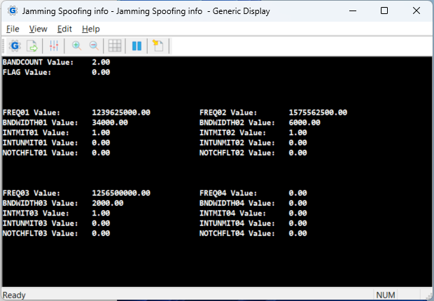
To do this, add a miscellaneous system to the project trough Db Setup. In the Generic Observation Definition page its possible to add the specific data from all the spoofing information.
The more general information can be found under ‘FLAG’ and ‘BANDCOUNT’.
Flag will have value 1 when spoofing is detected or value 2 when NMA checks fail.
There are cases in which Flag may have a value even when no interference is detected, we therefore recommend to use the Bandcount as a more accurate indicator of spoofing detection.
Whenever Bandcount has a value greater than 0 some form of interference is happening.
Per band that is experiencing interference there is extra information available under the observations ‘FREQ01', ‘BNDWIDTH01', ‘NOTCHFLT01’, 'INTMIT01’, and 'INTUNMIT01’.
The driver is able to show this information from up to 5 bands, from 01 trough 05.
The information displayed is the frequency of the band that experiences interference, the bandwidth, the band is suppressed by a notch filter manually, interference is detected and successfully mitigated, interference is detected and no mitigation is applied.
Setup Generic display
The observations that were added to the miscellaneous system in db setup can be displayer in the Generic display.
In the layout editor under the tab ‘RAW DATA’ under ‘Observation Systems’ items can be added to be displayed.
Trough the ‘Add’ button a new observation can be selected, here the Septentrio Miscellaneous system needs to be selected and the Observation that is to be displayed.
After this the sub item needs to be selected, this will need to be the ‘Value'.
With this added the Generic display can display all the Observations that need to be monitored.
Importing Layout
For the Septentrio there is a default layout that can be imported: Septentrio Spoofing.xml
After creating a new Generic display its possible this file to quicken the setup process.
This can be done trough 'File’ and then opening the .xml file.
This will setup the example layout, however it is required to check the datasource for the observations in the Layout Editor since these might vary per project.
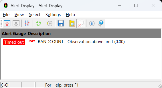
Setup Alert display
It is possible to keep track of spoofing using the Alert display.
The best way to do this is to add a new alert, of the category “raw data” and the type ‘Observation above limit’.
Set the upper limit to 0, and set the system to the miscellaneous Septentrio system, with and the Observation to ‘BANDCOUNT’.
This way the alert will display red whenever there is a frequency band that is being interfered on.
For a more advanced setup its also possible to check for the unmitigated interference, to only trigger the alert when there is interference that can not be mitigated.
Additional Information
As this is an active driver, it sends commands to the device:
After opening the port the driver will send: gso<CR><LF>. The device will reply with the gso message. This message is interpreted by the driver in order to find the stream to use.
This can either be a stream that is not used yet or the stream that it used before.
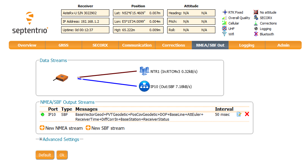
"SetSBFOutput, stream #id#, #port#,PVTGeodetic+PosCovGeodetic+DOP+BaseStation+ReceiverTime+ReceiverStatus+AttEuler+DiffCorrIn+BaseVectorGeod, #rate#"
#id# is replaced with the obtained available stream id, id is between 1-10.
#port# is replaced with the connection id, e.g. IP11 or COM3.
#rate# is replaced with a special string, e.g. msec100 for 10 Hz or sec1 for 1Hz.
This tells the device which blocks it needs to output, on which port and at what rate (mentioned above in the Database Setup).
This process can be re-initiated using the Reset IO from the Controller.
Drivers IO Notes
Command line parameter description for "drivers.io" file.
|
ACTIVE |
The driver configures the device to output certain SBF blocks which it needs, to decode the position, attitude and heading. |
|
SEPTENTRIO_SBF_ASTERX |
The driver will know that it has to boot in "Septentrio" mode. |
|
PPS (Time Synchronization) |
The driver will use the reported timetags (but only if a Time Synchronization system is interfaced in the Qinsy Template). |