
Description
-
Position data
The driver will automatically detect the position format from the first NMEA position sentence supported.
Driver will decode following NMEA sentences, containing (GPS or RTK) position data: $--GGA / $--RMC / $--GGK / $--GLL -
Quality
Driver can be used to decode quality information from the following NMEA sentences: $--GST / $--GSA / $PDAS,QUAL
It will automatically decode the supported NMEA quality sentences and copy the values to the previously decoded position data buffer. -
Heading
Driver will automatically detect the heading format from the first NMEA gyro string.
The driver is able to decode heading from the following NMEA sentences: $--HDT / $--HDG / $--HDM -
Metadata
Driver will decode metadata from the following NMEA sentence: $PTNL,AVR,
which is a Trimble proprietary message but can be used by other receivers (e.g. Septentrio).
Metadata is always decoded as generic observations from a Miscellaneous System.
Driver Information
Communication
The driver does not actively communicate with the positioning system; it listens to the incoming messages.
Three communication versions of the driver are available, but the internal workings of the drivers are the same except for the data reception:
-
Serial
-
Network version (UDP)
-
Network version (TCP)
Timing
The time tag of (all) the data is determined from the position sentence, i.e. the time tag of the (first) heading (after the position data) is copied from the position buffer update time.
However, the data buffers are not updated until the last sentence from an NMEA block is received. NMEA blocks are determined as follows:
Auto-Detection of NMEA Formats
-
After starting up, or after a "Reset I/O" command has been issued by the Qinsy Controller, the driver waits for the first NMEA position sentence that can be properly decoded.
The NMEA type of this sentence will determine the next NMEA position sentences that are decoded. -
All NMEA quality information sentences and NMEA gyro compass sentences that are received before the second NMEA position sentence will be considered to be part of one NMEA block.
-
The format of the last NMEA quality information sentence or NMEA gyro compass sentence will be used to define the NMEA sentence that will trigger an update of the driver data buffers.
There is a command line option to disregard gyro compass sentences as trigger strings. -
If only NMEA position sentences are received (during the auto-detection phase), then the driver position data buffer is updated for each valid NMEA position sentence of the right format.
-
Be aware that the auto-detection process will take at least two valid position sentences (twice the position update cycle time) after starting up the driver.
-
The auto-detection process will be restarted after each "Reset I/O" command.
Decoding Notes
Driver will not decode any xxGGA, xxGLL or xxGGK strings if the position fields are empty.
When an HDT String is available in the data but contains no values then the data will be decoded with quality flag -2 and will not be used.
Format
$GPGGA,,,,,0,00,1.0,00065.000,M,00000.000,M,0.00,*4D
Format Example
$INRMC,112545,A,2637.9681,N,05009.4071,E,00.0,182.3,240500,,*38<CR><LF>

$PTNL,GGK,172814.00,071296,3723.46587704,N,12202.26957864,W,3,06,1.7,EHT-6.777,M*48

$GPGGA,072840.20,5352.726971,N,00842.847935,E,0,00,1.0,00065.000,M,00000.000,M,0.00,*4D
$HEHDT,226.2,T*2B

$INGGA,120000.045,4928.46282,N,00008.01717,E,4,00,1.0,55.14,M,,,2.0,0001*34
$INGST,120000.045,,0.7,0.6,88.1,0.7,0.7,0.7*6C
$INGSA,A,3,1,3,5,7,9,11,13,15,,,,,1.1,2.2,3.3
$INHDT,52.7,T*15

$GPGGA,104101.07,5149.695871,N,00443.244094,E,19,06,2,13.864,M,47.176,M,1.0,0001
$PDAS,QUAL,0.018,0.018,0.023,5

$GLL,0447.01472,S,01151.07695,E,05,D,9,ID1
$HCHDM,162.3,M*2F
System Configuration
Driver can be used to decode '$PDAS,QUAL' quality messages after enabling them in a DSNP Aquarius RTK receiver by defining the following string in its Configuration Setup (KART Real Time solution):
'$PDAS,QUAL',',NPKRSD:1:3,',',EPKRSD:1:3,',',HPKRSD:1:3,',',MKIN
Database Setup
-
Positioning Navigation System
Select driver “NMEA Position and Heading”, “Network (UDP) - NMEA Position and Heading” or “Network (TCP) - NMEA Position and Heading”.
When you select the driver with the addition of "(No Checksum)" then the decoder will ignore the NMEA checksum which is normally at the end of each sentence.
The latency field is only used when there is no valid Time Synchronization system (PPS) present in your online setup. When there is a valid Time Synchronization system then the decoded time of the NMEA sentence is used for time-stamping -
Heading
When the NMEA input data block also contains a $xxHDT, $xxHDG or $xxHDM sentence, the driver can also be used to decode the heading data. The driver currently only supports True Heading observations.
If a HDM heading is obtained, magnetic variation should be entered as for example a (C-O) value, with negative values for westerly variations, since (C-O) values are added to the raw heading observations, or a $xxHVD or $xxHVM sentence should be included.
Values obtained from HDT and HDG strings are always true headings.-
Add a system of type "Gyro's and compasses", select the same NMEA driver and enter the same serial I/O parameters as with the NMEA position driver.
See the description under "GYRO SYSTEM DRIVERS". When this "NMEA Position + Heading" driver is used, a serial interface cable does not have to be split.
-
-
Miscellaneous System
In order to decode values from Trimble Proprietary sentence $PTNL,AVR add a Miscellaneous System and select driver entry containing “NMEA Position and Heading (Trimble $PTNL,AVR Metadata)”.
Use the same I/O parameters as the other NMEA heading and/or position driver.
On the next wizard page you add for each AVR field you’re interested in a generic observation: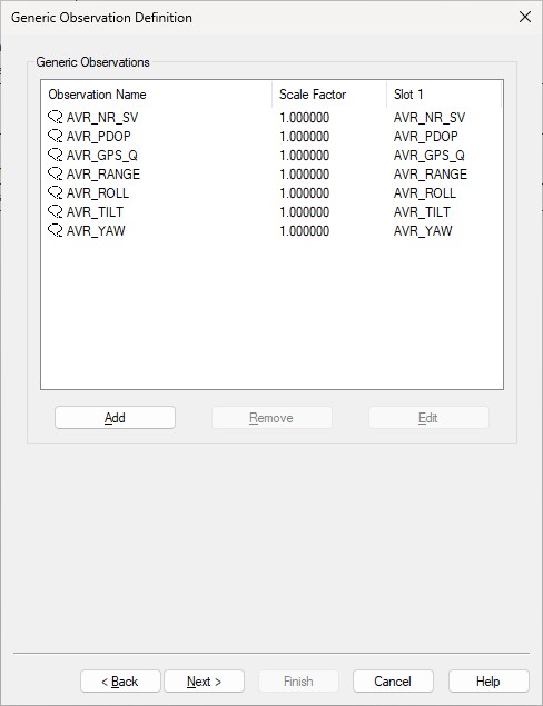
Here you can add up to seven generic observations that you may want to monitor.
Each generic observation needs a unique Slot Id so the driver knows which field to decode.
It is highly recommended to use the drop-down selection for the correct Slot Id: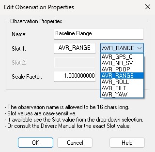
More convenient may be to use the checkbox to add all observations at once:
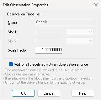
Of course you can change the default name for each observation as long as it doesn't exceed 16 characters.
Find below a table with all possible Slot IDs:
|
Slot 1 ID |
Observation |
Field number $PTNL,AVR sentence
|
|---|---|---|
|
AVR_YAW |
Yaw angle, in degrees |
#2 |
|
AVR_TILT |
Tilt angle, in degrees |
#4 |
|
AVR_ROLL |
Roll angle, in degrees |
#6 |
|
AVR_RANGE |
Range between antennas, in meters |
#8 |
|
AVR_GPS_Q |
GPS Quality Indicator |
#9 |
|
AVR_PDOP |
PDOP |
#10 |
|
AVR_NR_SV |
Number of satellites used in solution |
#11 |
Undocumented Slot 1 ID:
Add a generic observation with Slot “ROT” in order to decode the Rate Of Turn value (degrees per minute) from a NMEA $--ROT sentence.
On the third wizard page you can also change the default name of each observation as long as it doesn't exceed 16 characters. Leave all other parameters at their defaults
Online
-
Computation Setup
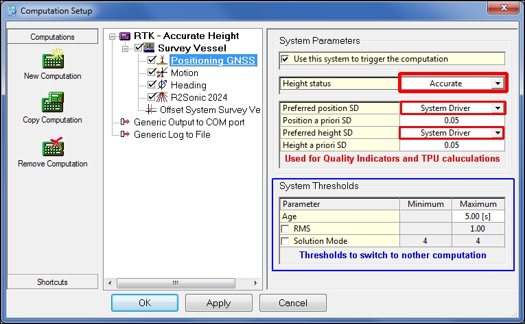
In the Controller one can choose which positioning components need to be used in computation.-
Unreliable Height - Tide
This means that the height of the positioning system cannot be trusted and that tide will be used as alternative height source. -
Accurate height - RTK
This means that the height reported by the positioning system is accurate and will be used as height component. -
Standard Deviations
The standard deviations (SD's) are used as Quality Indicators in the computation and for the TPU calculations.
There are 3 options:-
System Driver
The reported SD's by the positioning system (in the $xxGST string) will be used when available.
This means that the realtime SD's are used and these are the best option to get a more realistic view on the performance of your survey system. -
Computation Setup
These are the values entered in the computation in the fields: Position a priori SD and Height a priori SD (only in Accurate Height, otherwise SD of the Tide observation will be used).
These values are predefined values by the manufacturer or by experience when using them in a static environment.
They represent accuracies that can be achieved when the equipment is working accordingly. -
Database Setup
This is the value entered in Database Setup on page 2 of the device setup, under Position Parameters: A-priori SD.
This value will online be used:-
Position a priori SD = value
-
Height a priori SD = 2x value (only in Accurate Height, otherwise SD of the Tide observation will be used).
-
-
-
-
$xxGST and/or $xxGSA
-
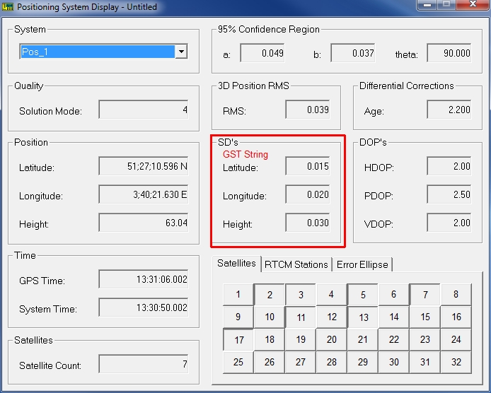
Positioning System Display
The statistical information from $xxGST and $xxGSA sentences are shown in a Positioning System Display.
The RMS value of the range inputs from the $xxGST sentence is displayed in the MDE box.
The age of the DGPS data from the $xxGGA sentence is displayed in the Unit Variance box.
When no $xxGSA sentence is available, the Satellites tab just indicates the number of satellites in use (decoded from $xxGGA sentence). -
Observation Physics Display
The standard deviations of the latitude, longitude and altitude (height) errors are shown in an Observation Physics Display as the so-called quality indicator of the corresponding positioning system observation.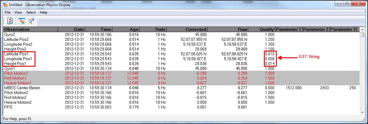
-
Alert Display
The various statistical measures can be used to define an alert and even to pause storage when such a value is above a certain limit.
Start up an Alert Display and add an alert of type "Raw Data Alert".
Possible alerts
-
|
Raw Data - Type |
Explanation |
$--GGA |
$--GST |
$--GSV |
|---|---|---|---|---|
|
Position mode outside limits |
alert on GNSS (RTK) solution mode value |
|
|
|
|
Differential Age above limit |
alert on age of GNSS corrections |
|
|
|
|
Number of Satellites outside limits |
Alert minimum required and maximum allowed satellites |
|
|
|
|
Position RMS outside limits |
alert on semi-major axis value |
|
|
|
|
Quality indicator outside limits |
alert on standard deviation (SD) values |
|
|
|
-
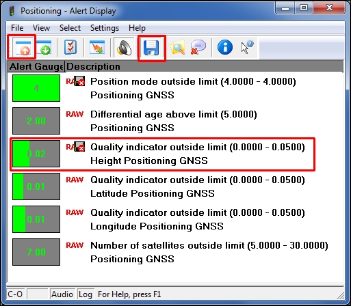
The position mode and position RMS alerts can only be defined for the (positioning) system.
The quality indicator (sd) alerts must be defined for the system and the specific observation, latitude, longitude or altitude (height).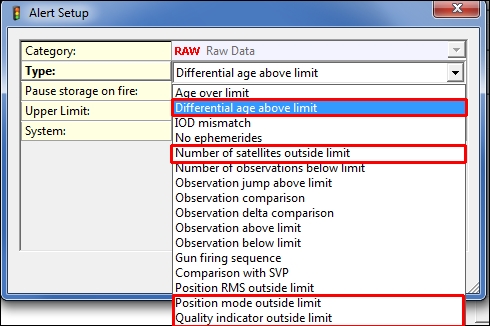
-
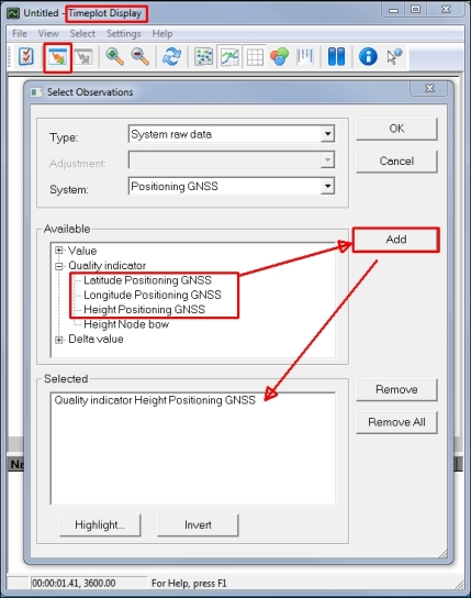
Time Plot Display
The Time Plot Display can be used to show the standard deviations reported by the $--GST string.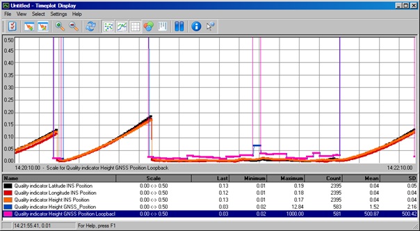
-
Positioning System Display
-
-
$PDAS,QUAL
-
Positioning System Display
The statistical information from $--GGA and $PDAS messages are shown in a Positioning System Display.
The RMS value of the $--GGA position inputs from the $PDAS message is displayed in the 'Quality measures - a' box.
The standard deviations of the latitude, longitude and altitude (height) values from the $PDAS messages are shown in the 'SD's - Latitude, Longitude, Height' boxes. -
Observation Physics Display
The standard deviations of the latitude, longitude and altitude (height) errors are shown in an Observation Physics Display as the so-called quality indicator of the corresponding positioning system observation. -
Alert Display
The various statistical measures can be used to define an alert and even to pause storage when such a value is above a certain limit.
Start up an Alert Display and add an alert of type "Raw Data Alert".
Possible alerts:
-
|
Raw Data - Type |
Explanation |
|---|---|
|
Position mode outside limit |
Alert on Kinematic Mode value in $PDAS message |
|
Position RMS outside limit |
Alert on combined standard deviation value from $PDAS message |
|
Quality indicator outside limit |
Alert on standard deviation (SD) value from $PDAS message |
The position mode and position RMS alerts can only be defined for the system.
The quality indicator (sd) alerts must be defined for the system and the specific observation, latitude, longitude or altitude (height).
Drivers IO Notes
It is not advised to change the Driver.io options if you do not understand the impact of the changes.
It is better to consult the Support department for a solid and durable solution.
The Drivers.io will be overwritten when installing a new Qinsy version if the date of the last update of the existing file is older than the one in the new installation CD / MSI.
-
NOCS
Command line parameter "NOCS" will disregard all checksum fields. -
NOTH
"NOTH" will not accept an NMEA gyro compass sentence as buffer update trigger sentence, i.e. the data buffers are updated after each NMEA position sentence (or accompanying quality sentence if one was encountered during auto-detection). -
parameters "1", "2" or "3"
Command line parameters "1", "2" or "3" are only applicable to GGA sentences.-
Add a "1" to the drivers.io command line to decode only the first field (if it is already the height above the ellipsoid),
-
Add "2' to decode only the second field. Be aware that the command line for the corresponding entry for the heading driver must also be changed.
-
Default is "3" which means that the height value is obtained as the sum of the first and second height fields in a GGA sentence, i.e. the antenna altitude field and the geoidal separation field.
-