
Description
Leica IPAS20 (Inertial Position & Attitude System) is an integrated georeferencing system.
It rigorously integrates raw data from a high-accuracy Global Navigation Satellite System (GNSS) receiver board with the raw data from an Inertial Measurement Unit (IMU) using a Kalman filter and outputs position, velocity, and attitude data at a high rate.
Driver Information
|
Driver |
Network - Leica IPAS20 |
Interface Type |
TCP-IP |
Driver Class Type |
Counted |
|---|---|---|---|---|---|
|
Yes |
Input / Output |
Input |
Executable |
DrvQPSCountedTcp.exe |
|
|
Related Systems |
|
||||
|
Related Pages |
|
||||
Decoding Notes
The driver is a network driver (TCP) that communicates with the IPAS20 on a port in the range 25002-25006.
A binary message received from the IPAS20 consist of the following parts:
|
Header |
Data |
Checksum |
Each message has a header with a common structure. The data part is the main body of the message. A CRC-32 checksum is used to calculate if the message received correctly. From the header, it can be determined what message type is received.
The message types decoded by Qinsy are as follows:
|
Type |
Description |
Update freq. |
Decoded by Qinsy as |
|
2001 |
GPS only solution |
1 Hz |
Positioning system (optional) |
|
2601 |
Integrated solution in the aircraft frame |
depends on IMU |
Positioning system (optional), Gyro, Pitch Roll Heave sensor, Acceleration Veolcity sensor |
|
4001 |
GPS satellite info |
1 Hz |
Positioning system |
|
4003 |
System Status |
1 Hz |
Miscellaneous system |
Concerning the positioning system, the user has the choice to decode the GPS only solution or the integrated solution, where the IMU data has been integrated with the GPS observations. The choice can be made by adding a different version of the driver in DbSetup. If the second option is chosen, it is strongly recommended to reduce the datarate in the IPAS controller software. Having a positioning system with, for example, a 200 Hz update rate, will slow down replay enormously. One should always consider if this is worth it.
All systems can have the same port number, except the GPS only positioning system. That system needs a different port number to communicate with the IPAS.
Also note that this system can use GPS, as well as GLONASS satellites for navigation. The positioning system display usually shows the GPS satellite numbers currently in use, but since it cannot show GLONASS satellites, it shows the number of satellites instead.
System Configuration
Start the IPAS controller, select the Log/Ethernet tab and connect though the master port. In that same tab, the port setup needs to be done. Select the port(s) through which Qinsy communicates with the IPAS.
See the following table for port numbers and their names in the Controller user interface.
|
Port name |
Port number |
|---|---|
|
TCP MASTER |
25001 |
|
TCP SLAVE 1 |
25002 |
|
TCP SLAVE 2 |
25003 |
|
TCP SLAVE 3 |
25004 |
|
TCP SLAVE 4 |
25005 |
|
TCP SLAVE 5 |
25006 |
Set the message rate of the raw integrated reference frame to 0, since Qinsy does not decode this message. We recommend to set the message rate of the raw integrated aircraft frame to 20 or 50 Hz.
Not too high, since that just slows down replay, while not really adding to the accuracy of your survey. See the screenshot below.
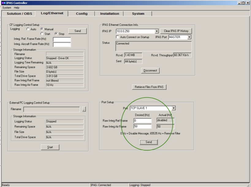
This walk through was written with IPAS controller software version 2.06. The user interface may look different in other versions.
Database Setup
In order to decode a position from the Leica IPAS20, add a Position Navigation System to your template database and select the driver "Network - Leica IPAS20" or alternatively if a gps only solution is needed select "Network - Leica IPAS20 (GPS only solution)". Enter the IP address of the system and enter a port number in the range 25002 to 25006.
-
In order to decode a heading from the Leica IPAS20, add a Gyro system to your template and select the driver "Network - Leica IPAS20 (Heading)". Enter the IP address and a port number in the range 25002 to 25006.
-
To decode the attitude from the Leica IPAS20, add a Pitch, Roll and Heave Sensor System to your template database and select the driver "Network - Leica IPAS20 P-R". Enter the IP address and a port number in the range 25002 to 25006. In the next page of the wizard, set the rotation type to HPR.
-
To decode GPS status and/or IMU status information from the Leica IPAS20, add a Miscellaneous system to your template database. Enter the IP address and a port number in the range 25002 to 25006. As slot ID, choose "IMU" for the IMU status info and "GPS" for the GPS status info.
-
To decode velocity east, north and up , add an Acceleration Velocity system to the template database. Enter the IP address and a port number in the range 25002 to 25006. Slot names are not needed, since there is only one input of every observation type supported.
It is recommended that all systems have the same port number, except the GPS only solution positioning system. That system should have a different port number from the rest.
Online
Note when online, that when the INS is out of alignment, it might output 0 values for heading, pitch and roll. Qinsy will flag these observations as invalid (-1) so they are not used in the computation, but they can be seen in the Observation Physics Display.
The following tables contain interpretations of the various quality indicator (qi) values that can be decoded from the IPAS system. Note that the qi values for the GPS only positioning system differ from the positioning system which decodes the full solution. These values are given here as a convenience only. For the precise meaning of these indicators, please contact Leica technical support.
GPS Only positioning system quality indicator
|
value |
Description |
|
-13 |
large residuals make position unreliable |
|
-11 |
negative variance |
|
-10 |
delta position is too large |
|
-9 |
residuals are too large |
|
-8 |
variance exceeds limits |
|
-7 |
height or velocity limits exceeded (in accordance with COCOM export licencing restrictions) |
|
-6 |
not yet converged from cold start |
|
-5 |
test distance exceeded (maximum of 3 rejections if distance > 10km) |
|
-4 |
covariance trace exceeds maximum (trace > 1000m) |
|
-3 |
singularity at parameters matrix |
|
-2 |
no convergence |
|
-1 |
insufficient observations |
|
1 |
position has been fixed by the FIX POSITION command |
|
2 |
position has been fixed by the FIX HEIGHT, or FIX AUTO command |
|
3 |
position has been fixed by the FIX VELOCITY command |
|
8 |
Velocity has been computed using instantaneous Doppler measurement |
|
16 |
single point position |
|
17 |
psuedo range differential solution |
|
18 |
solution calculated using corrections from a Satellite Based Augmentation System (SBAS) |
|
20 |
OmniSTAR VBS position (L1 sub-meter) |
|
32 |
floating L1 ambiguity solution |
|
33 |
floating ionospheric-free ambiguity solution |
|
34 |
floating narrow-lane ambiguity solution |
|
48 |
integer L1 ambiguity solution |
|
49 |
integer wide-lane ambiguity solution |
|
50 |
integer narrow-lane ambiguity solution |
|
51 |
RTK status where the RTK filter is directly initialized from the INS filter |
|
52 |
INS calculated position corrected for the antenna |
|
64 |
OmniSTAR HP position (L1/L2 decimeter) |
positioning system quality indicator
|
value |
Description |
|
-1 |
no solution |
|
1 |
initial solution assigned |
|
2 |
navigation |
|
3 |
GPS position update |
|
4 |
GPS velocity update |
|
5 |
GPS only solution |
|
6 |
ZUPT update |
|
7 |
smoothed solution |
|
8 |
in motion fine |
|
9 |
in motion transfer |
|
10 |
in motion coarse |
|
11 |
stationary fine |
|
12 |
stationary coarse |
IMU status
|
value |
Description |
|
1 |
unknown or no IMU data (if data is missing >= 1s) |
|
2 |
IMU data normal |
|
4 |
IMU data checksum error |
|
8 |
IMU data gaps <= 0.2 seconds |
|
16 |
IMU data gaps > 0.2 seconds |
|
32 |
IMU not license |
GPS status
|
value |
Description |
|
1 |
no satellite |
|
2 |
too few satellites |
|
4 |
3D single point solution |
|
8 |
DGPS solution |
|
16 |
float solution |
|
32 |
fixed solution |