Description
This driver is capable of sending 3 types of information to an IHC DigiSys system:
-
TIN triangles
-
Grid points
-
Center line definition
The first two types of information are sent on request and the latter is send when either side is starting up or if the used center line is modified/changed and finally if the optional redundancy status changes.
The information is exchanged by means of ASCII messages across a TCP connection.
The DigiSys system functions as the server and actively listens for new connection while the Qinsy system functions as client and initiates the connection by actively connecting to the DigiSys system.
Driver Information
|
Driver |
Network - IHC Dredging Triangles (DigiSys) |
Interface Type |
Network TCP |
Driver Class Type |
Terminated |
|---|---|---|---|---|---|
|
No |
Input / Output |
Input and Output |
Executable |
DrvOutIhcTcp.exe DIGISYS_ASCII |
|
|
Related Systems |
|||||
|
Related Pages |
|
||||
Coding Notes
TIN Triangles
The TIN triangles will only be sent when the DigiSys system asks for them.
The query message contains the following parameters:
-
Requested number of triangles
-
Maximum area length
-
Maximum area width.
It is assumed that the maximum area length & width are specified in Qinsy survey units.
Once a query message is received the driver it will perform the following steps:
-
Obtain the position of the selected output node as defined in the Controller.
-
Find the TIN triangle in which this node is located.
-
Find the neighbors of the TIN triangle found in step 2.
-
Repeat step 3 until the maximum number of triangles has been found
-
Create a rectangle around the position found in step 1.
-
Determine on which section of the center line the position from step 1 is located.
-
Rotate the rectangle from step 5 with the orientation of the section found in step 6.
-
Filter out any triangles for which one or more corners are not located within the rotated rectangle.
The driver will never output more than 500.000 triangles as this limitation is mentioned in the protocol definition document.
The resulting triangles are sent to the DigiSys system.
The output also contains some meta-information which consists of:
-
The name of the file from which the triangles originated
-
The name of the layer from which the triangles originated
-
The last modification date/time of the file from which the triangles originated.
In case the file from which the triangles originate is a grid file the driver will first create triangles from the regular grid.
In case a manual design is used the driver will send two triangles that represent an area of 500x500 survey units around the output node position.
Grid Points
The grid points will only be send when the DigiSys system asks for them. The query message contains the following parameters:
-
Requested number of points
Once a query message is received the driver will perform the following steps:
-
Obtain the position of the selected output node as defined in the Controller.
-
Compute the size of a rectangle which contains twice the number of points.
-
Offset the rectangle with the position from step 1.
-
Get all points within the rectangle from step 3.
-
Sort the points based on distance from the position of step 1.
The driver will never output more than 9.000.000 grid points as this limitation is mentioned in the protocol definition document.
The resulting points are sent to the DigiSys system.
The output also contains some meta-information which consists of:
-
The name of the file from which the points originated
-
The name of the layer from which the points originated
-
The last modification date/time of the file from which the points originated.
Center Line Definition
The center line will only be sent when:
-
Either side (Qinsy or DigiSys) is starting up
-
The used center line is modified/changed
-
The optional redundancy status changes
Once it has been determined that a center line definition should be sent, the driver will perform the following steps:
-
Walk over all sections of the center line line to gather the waypoints
-
Encode the general center line information
-
Encode the meta-information which consists of:
-
The name of the file from which the center line originated
-
The name of the center line
-
The last modification date/time of the file from which the center line originated
-
-
Encode the individual waypoint information.
The driver will never output more than 1.000 waypoints as this limitation is mentioned in the protocol definition document.
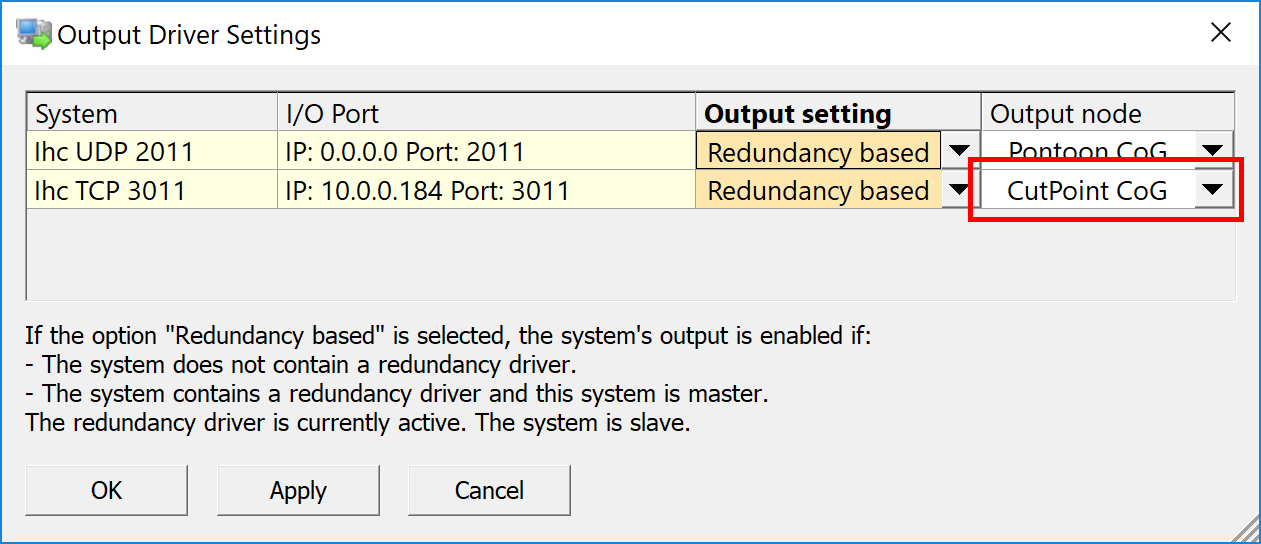
System Interfacing
When multiple DigiSys systems are available multiple copies of this driver may be added to the template database. In this case the drivers will communicate with each other so that if one instance of DigiSys sends a query for triangles or points the data will get send to all DigiSys instances.
This also applies for the center line functionality.
System Configuration
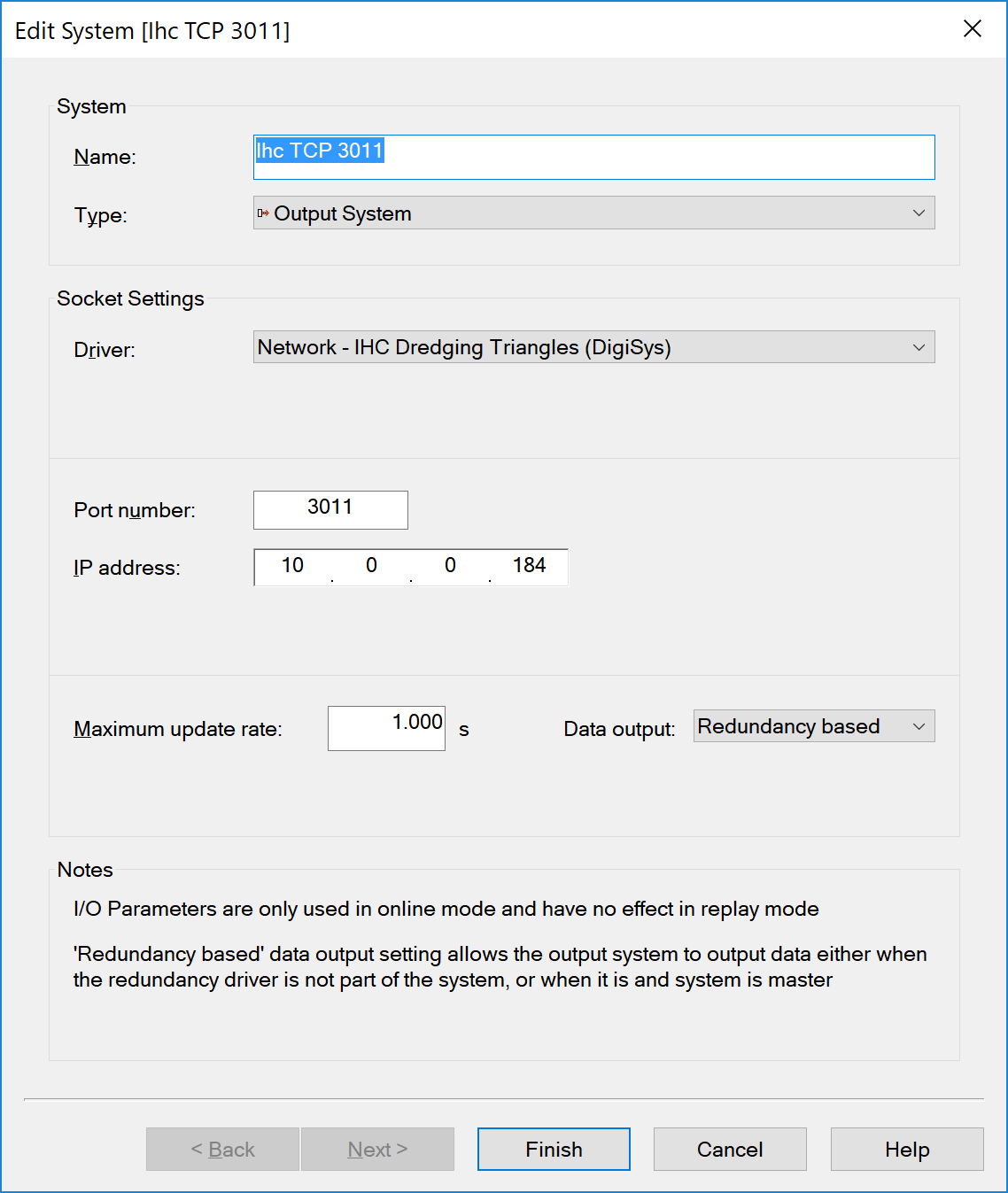
The DigiSys system should be configured to use the TCP port determined by the following formula:
DigiSys TCP port number = Qinsy TCP port number + last byte of Qinsy IP address.
So if the Qinsy PC has IP number 172.16.0.73 and port number is set to 3000 the port number that should be entered into DigiSys is 3073.
This was done to make it possible to exchange the Qinsy template file without changes when multiple Qinsy systems are running in a redundant setup.
Qinsy Configuration
Database setup
Select the IP number of the IHC dredging computer and set up correct port number. The port number should be the same as in the DigiSys system. By default this will be port 3000.
Important
Please be aware that the value entered in the 'Port number' field is only a base port number. The actual used port number is computed using the following rule:
DigiSys TCP port number = Qinsy TCP port number + last byte of Qinsy IP address.
So if the Qinsy PC has IP number 172.16.0.73 and port number is set to 3000 the actual port number used will be 3073. This was done to make it possible to exchange the Qinsy template file without changes when multiple Qinsy systems are running in a redundant setup.
Qinsy Online
Once the template has been taken online the driver does not show any UI.
The position of the output node as selected in the Controller is used as the center point in case a query is received for triangles or points.