Network - Crane Tool vdLeun (QATT) - 02
Description
Warning
This driver uses an old implementation of crane functionality where some calculations are done in the driver. It is recommended to use Object linking in combination with a rotation sensor.
For more information about object linking, use this document in the Qinsy Knowledge Base: 'How-to Object Linking'.
The Crane Tool VanDerLeun Driver decodes #QATT, #QXYZ and / or #QD messages from the Van Der Leun dredging computer that is mounted on board cranes used for dredging.
The dredging computer will deliver relative position, attitude and heading of one or more boom segments and the grab.
Qinsy will decode the position information as USBL, so it is not a real USBL system.
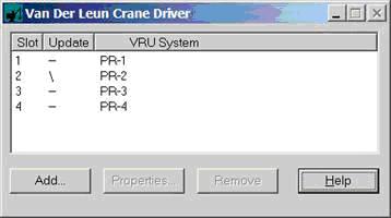
The driver has a user-interface for assigning the VRU systems to the slot information, this is not supported in Database Setup for these systems.
Two versions of the driver are available: a Serial version and a Network version (UDP).
The internal workings of the drivers are the same except for the data reception.
Driver Information
Coding Notes
Decoding Notes
#QATT messages contain a parent slot id. This slot id may be used for relative heading mode. Heading can be relative or absolute.
If relative, the heading is computed by adding the parent's heading to the decoded heading.
If pitch/roll/heading error flag is set (character 'E') then Quality indicators will be set to --1 else Quality indicator is set to +1.
Note
Observations with a negative quality indicator are not used in Qinsy. This can be checked with the Observation Physics display.
Driver does not convert units or conventions. Use the unit/convention settings in Database Setup.
Qinsy Config
Database Setup
The driver can decode three types of strings: the #QATT for heading and attitude, the #QXYZ for USBL and the #QD for the draught ("inzinking").
All strings contain a slot number.
For the heading, USBL and Draught system enter a slot number in Database Setup.
For the Attitude (VRU) system assign the slot number to a VRU system with the User interface. The relationships VRU system - slot number will be stored in the registry and are automatically retrieved when the driver starts.
If the VRU system is not selected in the User Interface then it will not decode any VRU data!

All Slot Numbers should be numerical!
Add a "Gyro" system, and select this driver. Select the same COM port as the USBL system. Select appropriate slot number and units.
Add a "Pitch Roll and Heave" system, and select this driver. Select same COM port as the USBL system. Select appropriate convention.
NOTE: Slot numbers can not be entered here. Do this when the Controller is started with the U/I of the driver.
Add an "Underwater Sensor" system to decode the draught value from the #QD message, and select the "Crane ToolVanderLeun (QD)" driver.
Add an ROV Depth observation or a Draft observation and define its slot number. The unit must be set to meters.Add a "Tidegauge" system to decode the tide.
Add a "Dredging sensor" system to decode dredge sensors.
Add a "Miscellaneous" system to decode generic observations.
Choose the same COM port and baud rate for all these systems. This way all systems will be supported by one driver program.
