
Description
Active driver with user interface to communicate with your Auto Pilot System on board.
-
Main purpose of this driver is to continuously send track offset information to the Auto Pilot so the unit knows what course to steer to stay on the survey line.
-
Secondly the user has the option to use a turning track during a line-change: a smooth track can be calculated to steer to the SOL of the next line.
-
And thirdly in the so-called Swath Coverage Mode you can direct the vessel to steer automatically, based on the previous swath coverage of your multibeam system, which means surveying an area without line planning.
Driver Information
Click here to expand driver information...
|
Driver |
AutoPilot (with turning track) |
Interface Type |
Serial / Network (UDP/TCP) |
Driver Class Type |
Output |
|---|---|---|---|---|---|
|
No |
Input / Output |
Output |
Executable |
DrvOutAutoPilotUI.exe DrvOutAutoPilotUIUDP.exe
|
|
|
Related Systems |
|
||||
|
Related Pages |
|
||||
Output Formats
The following output formats are supported:
- NMEA APA format - Autopilot Sentence "A"
- NMEA APB format - Autopilot Sentence "B"
- NMEA RMB - Recommended Minimum Nav Info
- NMEA XTE format - Cross track Error, Measured
- Euro500 format
- RobNav-AP9 format
- RobTrack / STS500 format
- Kongsberg TNT ($PRTNT,X)
NMEA output formats can be combined with an additional NMEA RMB/RMC output format in order to support autopilot units requiring this additional information.
Interfacing Notes
Click here for interfacing notes...
The driver is a so-called active driver which means it will send data to the sensor (Auto Pilot Unit). The driver does not expect to receive data from the sensor.
The default output update-rate is every second, but this can be changed in your Database setup.
There are three versions of this driver: a serial one (RS232) and two network based drivers (UDP / TCP).
The user-interface for the three drivers is exactly the same, only the I/O protocol is different.
-
For the serial driver version only a one-way cable wiring is needed
|
Auto Pilot unit |
|
Qinsy Computer |
||||||||
|---|---|---|---|---|---|---|---|---|---|---|
|
DB-25 |
Sensor |
or |
DB-9 |
Sensor |
|
DB-25 |
COM |
or |
DB-9 |
COM |
|
Pin 2 |
TXD |
|
Pin 3 |
TXD |
X |
Pin 3 |
RXD |
|
Pin 2 |
RXD |
|
Pin 3 |
RXD |
|
Pin 2 |
RXD |
<----- |
Pin 2 |
TXD |
|
Pin 3 |
TXD |
|
Pin 7 |
SG |
|
Pin 5 |
SG |
----- |
Pin 7 |
SG |
|
Pin 5 |
SG |
-
For the TCP network driver version a connection with a TCP Server (Auto Pilot unit) is required.
The driver will act as a TCP Client. -
The UDP network driver will just broadcast the data to the selected port number and IP address (mask).
Before you go online it is recommended to check for a valid network connection.
E.g use the ping command from the Windows Command Prompt: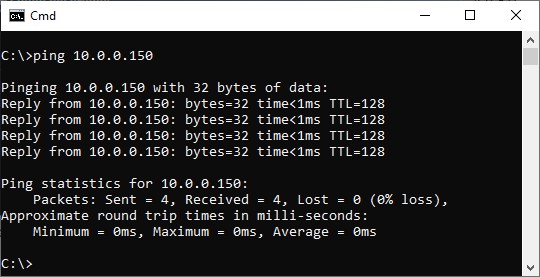
Just select Start from the Windows Task bar, Run..., Cmd <Enter>, and 'ping' the address of the autopilot unit.
Qinsy Setup
Click here to expand setup details...
Database
Add an output system to your template setup and select driver
-
"AutoPilot (with turning track)" for the serial, or
-
"Network - AutoPilot (with turning track) (TCP)" or
-
"Network - AutoPilot (with turning track) (UDP)" for the network version.
The output sentence format needs to be selected in the online Settings for these two driver entries.
However for the serial version (only) you could select here the driver entry with already the correct output format, e.g "AutoPilot (with turning track) - NMEA XTE"; this means that you can't change the output format while being online.
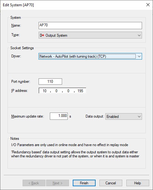
The maximum update rate tells the driver how often the formatted data sentence will be output to the autopilot unit.
Default update rate will be 1.000 s, which means every second.
In case you autopilot unit needs more often an update, e.g. 5 times per second then you should enter 0.200 s (in this case).
Qinsy Online
Click here to expand the online setup...
The Autopilot output driver has user-interface and therefore should be present in the Windows Taskbar.
When going on-line for the first time, locate the driver in order to view and change the settings to your requirements.
(In case the driver's dialog is not present in the Windows Taskbar, use the Controller's Driver Settings dialog to make it visible again: use pull-down menu Settings or keyboard shortcut Ctrl+H)
The driver's dialog has an upper pane and a lower pane; in the upper-pane you'll find user-definable settings and in the lower pane you'll see the results of the current situation.
Some settings are general and therefore always available and some settings depend on the selected output format.
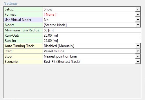
General Settings - Upper pane
|
Setup: |
Most settings (green rows) are only to be changed once; when going online for the very first time. Once everything is set up correctly it may be wise to hide them to prevent changing a setting by mistake, so here you can select to show or hide these setup settings. Note the third option Show+Advanced Settings: this will invoke on the next row an easy short-cut to access additional advanced settings, which normally only can be found using the dialog's upper-left corner icon menu. |
|
Advanced Settings: |
Use the [...] button (or double-click on the row) to invoke the Advanced Settings dialog. Note that these settings are also accessible via the upper-left corner icon menu. Go to the Advanced Settings paragraph (below) for a full description. |
|
Format: |
Main purpose of this driver is to continuously send track offset information to the Auto Pilot so the unit knows what course to steer to stay on the survey line. Select here the required output format that your auto pilot unit accepts:
A change will be effective immediately and can be seen in the lower Results pane. Please see the Format Specific Settings below for additional settings that come with the selected format. This option to select the format is only visible when you didn't specify the required output format in your template database setup, so i.e. only when you've selected driver:
|
|
Additional Output: |
This setting is only visible when one of the NMEA output formats is selected. The selected NMEA output format can be combined with an additional NMEA RMB/RMC output format in order to support autopilot units requiring this additional information. |
|
Use Virtual Node: |
For the best result it may be needed to define a steering node some meters ahead of the vessel (e.g. half the vessel length), or close to a location of the vessel's rotation point. This all depends on your vessel characteristics / behavior. Here you may use a 'virtual' calculated node position to influence the performance of the autopilot steering unit.
|
|
Baseline Direction: |
This setting is only available when using a virtual extended node baseline. The virtual node will be 'moved' forward over a certain distance, and the direction used should come from the vessel's course over ground (COG) or its heading. |
|
Baseline Length: |
This setting is only available when using a virtual extended node position. Enter a positive value, in survey units, to 'move' the selected node forwards, enter negative to 'move' backwards. |
|
Prediction Time: |
This setting is only available when using a virtual predicted node position. The driver can calculate where the selected node will be, after this 'prediction time' value, in seconds. The calculation is very powerful, because next to the vessel's speed, COG and heading, also the rate-of-turn is used. Realistic results can be expected if you use a prediction time of not more than 60 [sec], and when Kalman filtering is enabled in the Controller's Computation Setup. The distance between the actual node and the predicted position can be monitored in the Results part of the dialog (lower pane). Notice that there is an option in each Navigation Display, to show the predicted vessel shape. Open a Navigation Display, go to View Properties, Objects, select your vessel object, expand the Trail Settings option and enable 'show prediction'. Enter the same prediction time, and now you may graphically monitor how well the calculated prediction behaves. |
|
Node: |
The position of the selected node will be used to calculate the line offset with respect to the current survey line.
Note that it depends on the 'Use Virtual Node' setting whether the exact node position is used, or a 'virtual' one. |
|
Computation: |
This setting is only available when you have selected your own node name from the Node list.
|
|
Minimum Turn Radius: |
Enter the minimum turn radius (in survey units) of the vessel. In order to calculate a smooth turning track, two turns will be used, one when departing the start-point, one when approaching the stop-point.
If you enter a minimum turn radius of zero, the turning track will always be a straight line from start to stop, so no curves. |
|
Run-Out: |
Enter a value in survey units if you want to extend the previous line, prior commencing the first turn of the turning track. This might be useful to allow e.g. a towed fish to end the previous line. A negative value is allowed, but not recommended. Note that this extra run-out value comes on top of the value you may have entered in the Controller's Session Setup, to extend the survey line. |
|
Run-In: |
Enter a value in survey units if you want to approach the SOL of the new line in a straight line, e.g. to settle the ships attitude. A negative value is allowed, but not recommended. Note that this extra run-in value comes on top of the value you might have entered in the Controller's Session Setup, to start before the actual survey line. |
|
Auto Turning Track: |
|
|
Start |
Here you select the start-point of the turning track.
|
|
Stop: |
Here you select the end-point of the calculated track, which is the beginning of the new line. Normally you select "Nearest point on Line", in a rare occasion you might go for the other side, e.g. when the vessel is far away from the new SOL. |
|
Scenario: |
A maximum of six scenario's are possible to go from the start to the stop-point. So when commencing the turning track a vessel may turn to port (left turn) or to starboard (right turn) and approaching the stop-point can also be from port or from starboard. Use a Navigation Display to view the outcome of the selected scenario.
Note that some scenario's are not always possible (mathematically) with current settings and situation. |
|
Extend Start of Track: |
Normally the first waypoint of the turning track will be at the selected start (Vessel or Line). You may extend this start with a given distance [in survey units]. This means that the first waypoint will be in front of the selected start location. Note:
|
|
Extend Stop of Track: |
Extend the last waypoint of the turning track with an extra distance [in survey units]. Note:
|
Format Specific Settings
NMEA format settings
These additional settings will be available when one of the NMEA specific format is selected:
|
NMEA Talker: |
Two characters should be entered, and will be part of the first field of the outputted datastring. For example 'GP' will result in an output string that starts with "$GP". The result can be immediately seen in the lower Results pane of the dialog. When the Kongsberg TNT ($PRTNT,X) format is required it is recommended to enter 'PR' otherwise the Auto Pilot unit may not recognize the datastring |
|
Unit: |
Select the unit of the outputted cross-track error value (XTE). It is by default set to Meters ('M'), but you may also select Nautical Miles ('N') or International Feet ('f'). |
|
XTE Resolution: |
The number of decimals for the outputted cross-track error (XTE) value, and is default set to 3. |
|
XTE Offset: *)
|
The outputted cross track error value (XTE) will be appended with this offset and is by default set to 0.0. You may enter a negative offset value in order to decrease the outputted cross track error. The entered value will be displayed with a red color if it isn't equal to 0, as an extra reminder to the user. |
|
XTE Scalefactor: *)
|
The outputted cross track error value (XTE) will be multiplied with this scale factor, and is by default set to 1.0. You may increase this value e.g. to 10 or 100 in order to address high-performance autopilot systems. Note that if the scale factor is set to zero, the outputted XTE will also be zero. The entered value will be displayed with a red color if it isn't equal to 1, as an extra reminder to the user. |
|
*) The outputted cross track error value = (actual cross track + XTE Offset ) * XTE Scalefactor When using a non-default XTE Offset and/or Scalefactor you will see both results in the Cross Track Error field of the Results pane: first the actual cross track error (plus unit) and between brackets the outputted cross track error value. |
|
Euro500 format settings
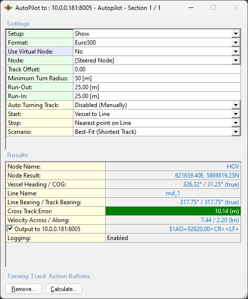
This additional setting will be available when the Euro500 format is selected:
|
Track Offset: |
Enter a value in survey units. The outputted off track will be the calculated one MINUS this value. |
RobNav-AP9 format settings
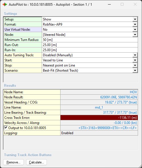
No extra settings are needed when the RobNav-AP9 format is selected.
A description for all the settings can be found in the General Settings paragraph.
RobTrack / STS500 format settings
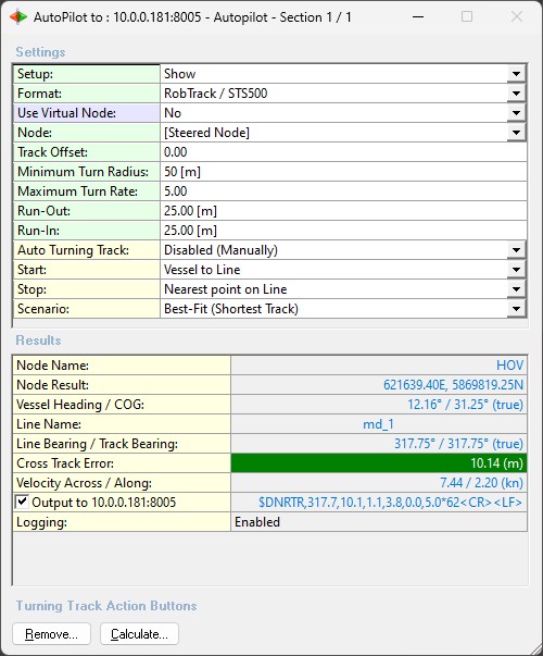
These additional settings will be available when the RobTrack / STS500 format is selected:
|
Track Offset: |
Enter a value in survey units. It will be pasted in field number six of the output datastring. |
|
Maximum Turn Rate: |
Enter a value in sec/deg. It will be pasted in field number seven of the output datastring. |
Kongsberg TNT ($PRTNT,X) format settings
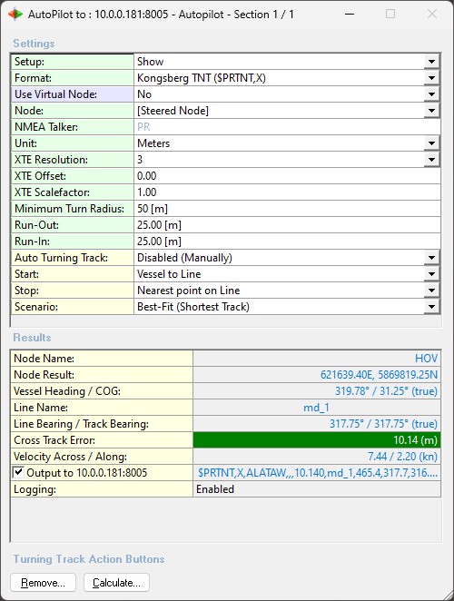
These additional settings will be available when the Kongsberg TNT ($PRTNT,X) format (NMEA look-a-like) is selected:
|
NMEA Talker: |
Two characters should be entered, and will be part of the first field of the output datastring. It is recommended to enter 'PR' otherwise the Auto Pilot unit may not recognize the datastring. Other characters are allowed but will be colored red to remind the user. The result can be immediately seen in the lower Results pane of the dialog. |
|
Unit: |
Select the unit of the outputted cross-track error value (XTE). It is by default set to Meters ('M'), but you may also select Nautical Miles ('N') or International Feet ('f'). |
|
XTE Resolution: |
The number of decimals for the output cross-track error (XTE) value, which is by default set to 3. |
|
XTE Offset: *) |
The outputted cross track error value (XTE) will be appended with this offset and is by default set to 0.0. You may enter a negative offset value in order to decrease the outputted cross track error. The entered value will be displayed with a red color if it isn't equal to 0, as an extra reminder to the user. |
|
XTE Scalefactor: *)
|
The output cross track error value (XTE) will be multiplied with this scale factor and is by default set to 1.0. You may increase this value e.g. to 10 or 100 in order to address high-performance autopilot systems. Note that if the scale factor is set to zero, the output XTE will also be zero. The entered value will be displayed with a red color if it isn't equal to 1, as an extra reminder to the user. |
Swath Coverage Settings
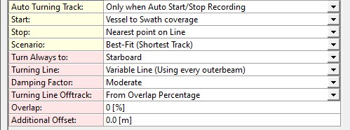
These red-row-colored settings are only visible when in so-called Swath Coverage Mode.
This means that the Auto Turning Track option is set to 'Only when Auto Start/Stop Recording' and Start is 'Vessel to Swath coverage'.
|
Turn Always to: |
Select to which side the vessel has to move after stop recording in order to start recording for the next session. The first two are relative to the last heading direction, the other ones (compass rose directions) are independent from any line bearing or heading.
Selecting one of the compass rose directions is useful when surveying an area: 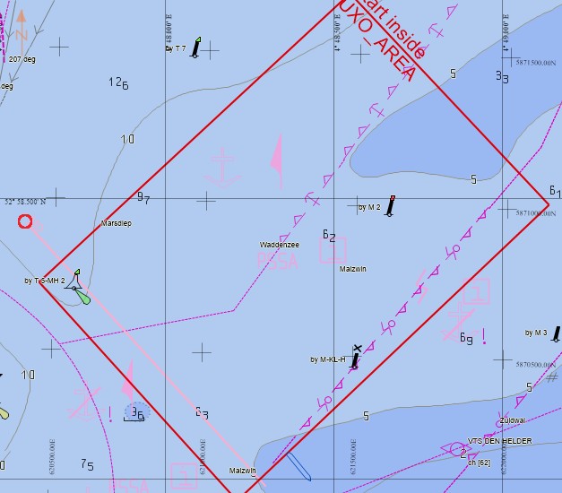
In this example the survey commences at the south-west side (following the pink line) so in order to auto survey the entire area you should select 'NE'. Changing this setting when your vessel is 'outside' the selected survey area will automatically re-calculate the (current) turning track .
|
|
Turning Line: |
Below two examples of the turning track based on the same swath coverage: 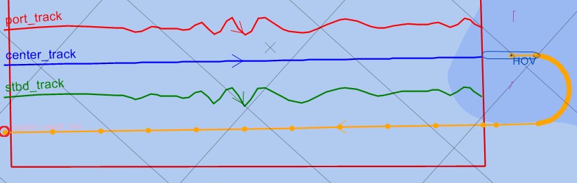
Changing this setting when your vessel is 'outside' the selected survey area will automatically re-calculate the (current) turning track .
|
|
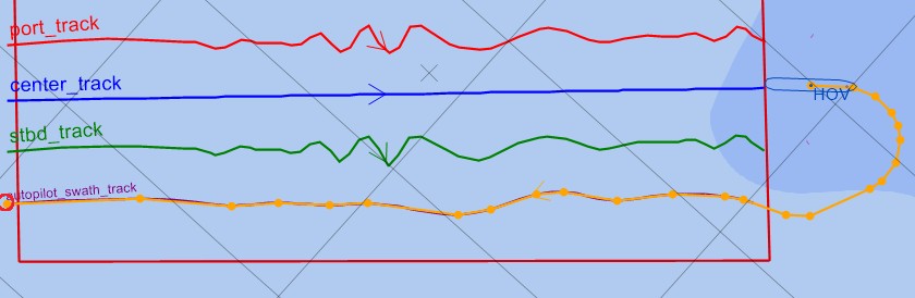
Damping Factor: |
The damping factor is used when the turning track is based on 'Variable Line (Using every outerbeam)'.
Use your Navigation Display to see the outcome when changing the damping factor.
Below three examples of the turning track based on the same swath coverage, the first using 'None', the second one 'Moderate' and the third one 'Heavy': 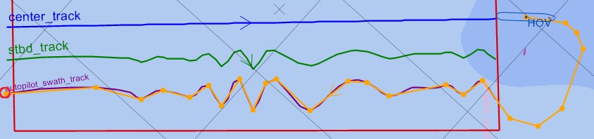
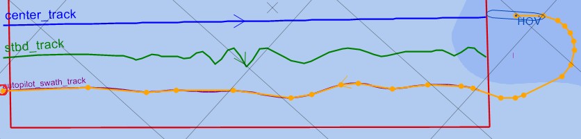
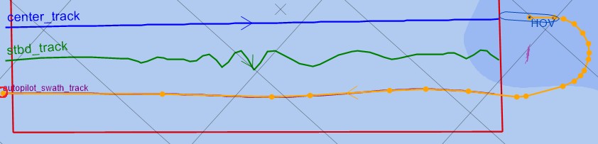
Changing the damping factor when your vessel is 'outside' the selected survey area will automatically re-calculate the (current) turning track .
|
|
Turning Line Offtrack: |
Changing this setting when your vessel is 'outside' the selected survey area will automatically re-calculate the (current) turning track .
|
|
Overlap: |
This setting is only visible when the Turning Line Offtrack setting is 'From Overlap Percentage'. Enter a percentage value between 0 and 100 % 0% means the same line back as the past outer beam track plus half of the entire swath width: 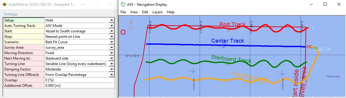
100 % means the same line back as the past outer beam track: 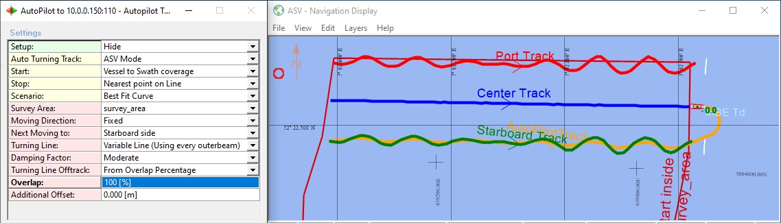
Changing the overlap when your vessel is 'outside' the selected survey area will automatically re-calculate the (current) turning track .
|
|
Additional Offset: |
This extra offset will always be added to the calculated turning track line. You may enter a negative value in order to allow extra overlap for the next recording. Changing the offset when your vessel is 'outside' the selected survey area will automatically re-calculate the (current) turning track .
|
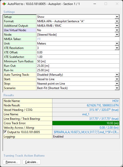
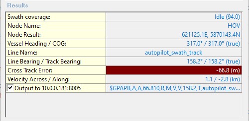
Results - Lower pane
Use the lower pane to see the calculated results for current situation and settings.
Here you can also quickly disable the output to the autopilot unit if desired.
|
Swath Coverage: |
This row is only visible in Swath Coverage Mode. It shows the status whether the driver is collecting outer beam information for the swath coverage or not.
The incrementing value between brackets indicates the duration (in seconds) for this status |
|
Node Name: |
The name of the selected node which current location is used to determine the cross-track error. When using a virtual node it will be mentioned here. |
|
Node Result: |
The current position of the selected node, in grid co-ordinates, which is used to determine the cross-track error. When using a virtual node position, it will be the position of the virtual node. |
|
Predicted Distance: |
This result is only visible when using a virtual predicted node position. It reflects the distance between the actual node position and the calculated predicted position, using the prediction time setting, the current heading and rate-of-turn of the vessel. |
|
Vessel Heading / COG: |
The current heading and course over ground (COG) of the vessel. The displayed rotation convention (true or grid) depends on the global project settings, which you can set in the Console. When using a virtual predicted node position, the heading will be the predicted heading, also, no COG will be displayed, because it is not calculated for the predicted node. |
|
Line name: |
The name of the current line, or the label "Turning Track to" the current line, in case the turning track is used. |
|
Line Bearing / Track Bearing: |
Line bearing of the current line and the bearing of the closest section of the turning track. The displayed rotation convention (true or grid) depends on the global project settings as entered in the Console's Settings. |
|
Cross Track Error: |
The calculated distance across (XTE), in survey units, of the current node position and the turning track or mainline.
Note that when using an additional (non-default) XTE Offset and/or Scalefactor you will see both results: first the actual cross track error and between brackets the outputted cross track error value. |
|
Velocity Across / Along: |
The across and along speed of the vessel. The across speed will be positive when heading to starboard, negative when heading to port. The unit depends on the current global project speed unit setting, which can be set in the Console. |
|
Format: |
The name of the selected output format. The format can be changed in your template setup. Note that this row won't be visible when you are able to select the Format in the upper Settings pane. |
|
The ASCII data string that will be outputted to the selected serial COM or network TCP port. If you disable the checkbox it will put the data output on hold. In that case values will be updated in the Results, but are displayed in gray. Disabling the data output (temporarily) can be useful to experiment with some settings, without disrupting the Auto Pilot unit too much by sending extreme values to it. |
|
Logging: |
This row is only visible when Advanced Setting 'NMEA Logging' is enabled. |
Notes
-
The number of decimals for all displayed values depend on the display resolution as defined by your Global Settings (Console).
-
All displayed values will be colored gray when the Output to the I/O (checkbox) has been disabled.
Examples
-
This is an example of the lower pane when no valid node results have been received yet at startup:
Example during initialization time
Just be patience and wait for the initialization to finish... -
This is an example when the current mainline is used to determine the cross track error
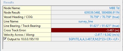
Example when the mainline is used
The 'Line name' row displays the name of the current mainline
The 'Cross Track Error' row is colored red when the node location is at port side and colored green when at starboard side. -
This is an example when the calculated turning track is being used:
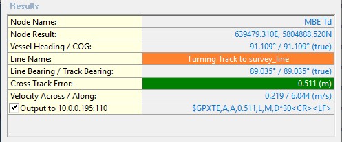
Example when a turning track is calculated
The 'Line name' row is colored orange and the name of the current mainline is preceded with 'Turning Track to'.
The 'Cross Track Error' row is colored red when the node location is at port side and colored green when at starboard side. -
This is an example when no network connection could be made between the Qinsy computer and the Auto Pilot unit:
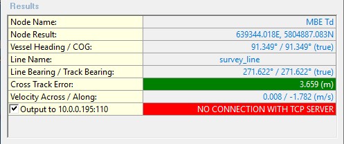
Example when there is no network connection
When this happens please check the network connection before you continue.
See the Interfacing Notes paragraph for more about the network connection.
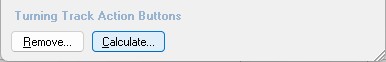
Turning Track Action Buttons
To overrule any automated action you can always use these buttons for a manual intervention.
|
Remove... |
This will invoke a dialog that allows the user to manually remove the current calculated turning track and from that moment on the driver will use the co-ordinates of the Controller's mainline again in order to determine the cross track error (XTE or distance across). The exact remove action upon OK depends on the current situation and settings. 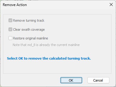
When an option is grayed out it means it can't be changed for current situation so that option will be the default. For example in the above dialog the turning track will be removed (first checkbox) and the collected swath coverage will be cleared (second checkbox).
So after this action you can't manually calculate a new turning track to the past swath coverage; but the driver will start collecting new outer beam information as soon as the Controller started the auto recording. The option to restore the original mainline is only applicable when Advanced Setting 'Update Controller Mainline' is enabled. In that case the mainline was (temporary) replaced by the 'autopilot_swath_track'. |
|
Calculate... |
This will invoke a dialog that allows the user to (re-)calculate the turning track using the current settings. You may use this at any time. Use the Navigation Display to monitor the outcome. In the Line Name field of the Results pane you will see the label "Turning Track to..." to indicate that the driver is using the calculated turning track in order to determine the cross-track error (XTE). Additionally the field is also colored orange. 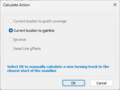
When an option is grayed out it means it can't be selected for current situation.
|
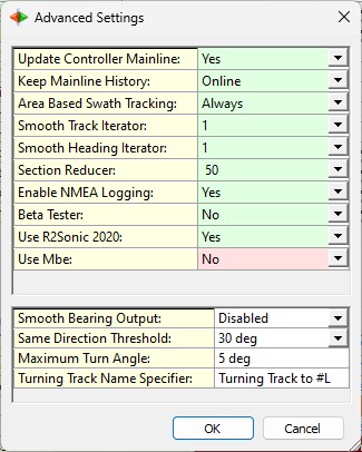
Advanced Settings
The advanced settings can be found using the dialogs upper-left icon menu or by double-clicking on the Advanced Settings row in the general setup
|
Update Controller Mainline: |
This setting has only effect when in Swath Coverage mode. This will activate immediately the new turning track as current mainline. So this new mainline is an exact copy of the turning track, based on the swath coverage, but without the turn to the start of it. Line name will always be 'autopilot_swath_track' Default setting is Yes. Track can be found in layer 'ACTIVE' and stored in the project's LineData subfolder with filename 'autopilot.qgfline'. |
|
Keep Mainline History: |
This setting has only effect when in Swath Coverage mode. This will keep a history of all previous calculated turning tracks where each track will be suffixed with an incrementing number.
All tracks can be found in layer 'HISTORY' and stored in the project's LineData subfolder with filename 'autopilot.qgfline'. |
|
Smooth Track Iterator: |
This is a filter setting and has only effect when in Swath Coverage mode. The calculated turning track may be affected by erratic outer beam behavior so in that case you should increase the iterator value to make the track smoother. The default value will be 1, 0 means no filter strength applied at all. It is safe to change this value when your vessel is still 'inside' the selected survey area: nothing will happen.
|
|
Smooth Heading Iterator: |
This is a filter setting and has only effect when in Swath Coverage mode. The calculated turning track may be affected by unstable heading behavior of the transducer so use this setting to filter the original heading values. Note that in general such unstable heading behavior is expected on very small boats (unmanned or autonomous vehicles). 0: means no filter (original heading values) 1: is the default filter strength 4: is the strongest filter strength 5: means that a fixed value is used which is derived from the sailed start to end bearing It is safe to change this value when your vessel is still 'inside' the selected survey area: nothing will happen. When the vessel is 'outside' the survey area then closing this dialog will automatically re-calculate the (current) turning track. |
|
Section Reducer: |
This is a filter setting and normally only useful when in Swath Coverage Mode. The number of sections for the calculated turning track (based on the swath coverage) will be reduced by this number Below two examples of the same calculated turning track, the first one with a maximum of 25 sections and the second one with a maximum of 100 allowed sections: 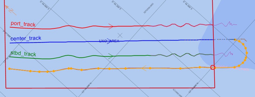
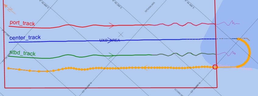
Less number of sections may result in a more stable autopilot behavior.
|
|
Enable NMEA Logging: |
All settings and all navigation data (NMEA) will be logged and therefore can be used afterwards for debugging purposes or reproducing the online behavior of your ASV. Yes will be the default. Two files are created and appended automatically every time you come online with the following filename convention:
Location will be the current project's LogFiles folder. |
|
Beta Tester: |
As a beta tester you'll get access to Abort / Resume Mission functionality. |
|
Use [ Your System Name ]: |
This setting has only effect when in Swath Coverage mode. The swath width of this system will be used when enabled and therefore affects the turning track calculation.
This row is repeated for every available singlebeam/multibeam/multi-transducer/laser system defined in your template database setup. Example for a commonly used setup could be:
|
|
|
|
|
|
|
|---|---|
|
Smooth Bearing Output: |
Enabling the Smooth Bearing Output is only recommended to use in Swath Coverage mode.
Which NMEA field is affected when this setting is enabled?
|
|
Same Direction Threshold: |
This setting affects the minimum turn radius in order to approach the next line. It means that when the vessel (start point) is already approaching the line (i.e. both have same direction) then the track to follow will be just 'connecting the dots' instead of using mathematical turns.
Below two examples of the same situation where the vessel is more or less approaching the next line: 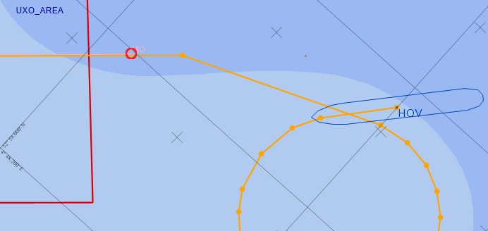
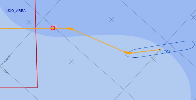
The first one (with no threshold) would be the mathematical correct outcome but may result in an unwanted extra turn in order to approach the line. The second example uses the default 30 degree threshold so in this case no unwanted/unnecessary turn was added. |
|
Maximum Turn Angle: |
Set the maximum turn angle for the turning circle sections. A turn angle from one section waypoint to the next will never exceed this value. Enter a value between 1 and 30 deg The default maximum turn angle is 5 deg Below two examples of the same calculated turning track, the first one with a max turn angle of 1 and the second one of 30 degree: 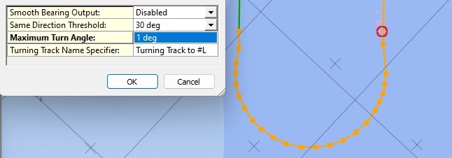
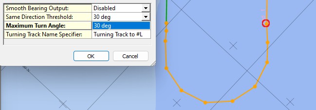
Playing with his setting may affect the behavior of your auto pilot unit: ever section change along the turn will output a different 'cross track error' and 'heading-to-steer' - change. |
|
Turning Track Name Specifier: |
When a turning track is used for the cross track error calculation instead of the Controller's mainline then this format specifier is used to name it.
Here you may overrule the default naming with your own free text, plus the following format specifiers:
The default name for the calculated turning track will be "Turning Track to <current line name>". Note that this track name will be part of most NMEA output formats. Useful option to overrule the default name in case your autopilot unit does not accept names which are too long. |
Display
Click here how to visualize the track...
Navigation Display
The calculated turning track can be made visible automatically in your Navigation Display:
Open your Navigation Display, select 'View Properties', 'Layers', 'Line Planning' and make sure to check the 'AutoPilot turning track' option.
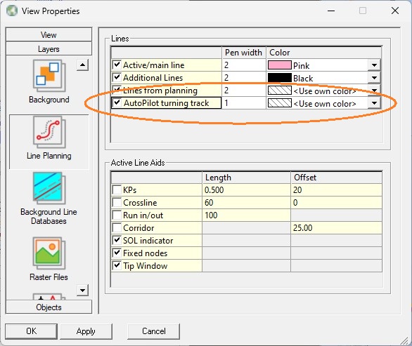
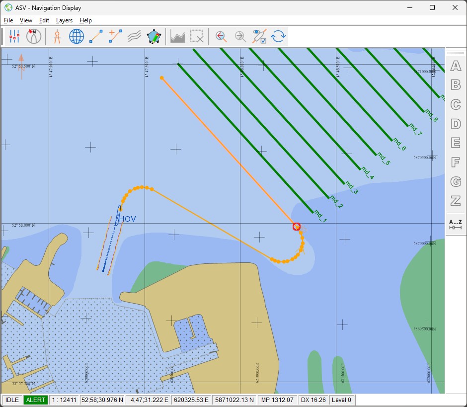
With the settings from the above example, the Navigation Display may look like this, after hitting the Calculate Turning Track button:
Tip
Every time when the turning track is calculated or changed, it will be refreshed by the Navigation Display within 5 seconds.
It is recommended to decrease this default 'refresh time' for a much faster response of your display. How?
Just select 'View Properties', 'View', 'User Interface' and set the 'File change check interval, in seconds' option to 1.
Note that the default (own) color of the turning track is orange and the individual straight sections in the turn are connected with orange circles.
Use the same View properties to change this turning track orange color in order to select your preferred one.
The circle icons can also be modified but for this you need to change the following registry key of the AutoPilot driver while being offline:
\HKEY_CURRENT_USER\Software\Qps\QINSy\8.0\Drivers\DrvOutAutoPilotUITCP\<Driver's Name>\Settings\Advanced - Icon Name
Possible values for this key are "icon_dot", "icon_solid_circle", "icon_open_circle", "icon_solid_square", "icon_open_square", "icon_plus", "icon_x", "icon_forward_arrow" or "icon_backward_arrow".
You may also enter the name of an existing graphics file located in the C:\Program Files (x86)\Common Files\QPS\CadIcons folder, but without file extension, e.g. "Star Yellow".