
Description
Driver to decode NMEA-0183 $NDPPU and $PADN,ATT sentences containing navigation position, baseline lengths and attitude information. If the $NDPPU message is valid, a USBL observation is computed for baseline one. If the $ADN,ATT sentence is also valid, another USBL observation is computed for baseline two. This driver can be used with the ADX Portable Pilot Unit from AD Navigation, both the ADX XR three pod system and the ADX XM four pod system.
Apart from reading and decoding these sentences, this driver can also send commands to the ADX MPU main CPU and the MPU dual modem. This functionality is used by the driver to display status information for both modems and to select an RTK network.
Driver Information
|
Driver |
Network - AD Navigation ADX-Series |
Interface Type |
TCP/IP |
Driver Class Type |
TCP Client, Terminated <LF> |
|---|---|---|---|---|---|
|
Yes |
Input / Output |
Input |
Executable |
DrvQPSTerminatedUITCP.exe |
|
|
Related Systems |
|
||||
|
Related Pages |
|
||||
Interfacing Notes
The MPU pod transmits the ADX data to the Qinsy computer over WLAN (WiFi local area network). Protocol: WLAN 802.11b/g, AdHoc network.
The SSID and IP address for the ADX system is displayed on the label underneath the MPU pod. For example, the SSID is "ADX 100" and the IP address is 10.33.3.3 (port 8023).
The WLAN card on the Qinsy computer must be set with a fixed IP address for the TCP/IPv4 protocol. The IP address needs to be within the same range as the IP address on the MPU, e.g. 10.33.3.100. The Subnet mask is 255.255.255.0.
How to connect to ad-hoc WiFi networks in Windows 8.1
Because the wireless network picker in Windows 8.1 doesn't show ad-hoc networks, connecting must be done by hand.
To see all networks in range, including ad-hoc, run this command in command shell (cmd.exe):
> netsh wlan show networks
SETUP
This must be done once per network:
• go to "Network and Sharing Center" by right-clicking network icon in notification area
• click "Set up a new connection or network"
• double click "Manually connect to a wireless network"
• enter the SSID "ADX 100" of the ad-hoc network (as shown by "netsh wlan show networks") into the "Network name" field
• configure security settings accordingly, i.e. Authentication: Open, Encryption: None
• uncheck "Start this connection automatically" (important)
• click "Next", then "Close"
Run this command (important):
> netsh wlan set profileparameter name="ADX 100" connectiontype=ibss
CONNECT
After setting up, run this command whenever you want to connect:
> netsh wlan connect "ADX 100"
Hovering over WiFi icon in system tray will show the name of the network that you are currently connected to, even if it's an ad-hoc network (the network picker will not show it if it's ad-hoc). The name is also visible in "Network and Sharing Center" window.
DISCONNECT
To disconnect from the ad-hoc network: connect to a different network, turn off WiFi, or run this command:
> netsh wlan disconnect
CLEANUP
To remove the network profile from Windows, run this command:
> netsh wlan delete profile name="ADX 100"
Setup Files
The AD Navigation ADX-Series driver can use two XML setup files
MobileNetworkProviders.xml
Contains the information needed to convert decoded MCC and MNC codes to a mobile network provider name and is part of the Qinsy installation
AdxRtkSettings.xml
Contains the RTK network settings that can be send to the ADX MPU modems and can be created (or edited) online.
If the ADX has also been used as part of the ADX Portable Pilot Unit from AD Navigation, the Qastor file can also be used by copying it to <common documents>\QPS\Shared\Drivers\Settings (<common documents typically resides at C:\Users\Public\Documents)
Availability of Qinsy sub folder in public documents
If the sub folder of the <public documents> folder does not yet exist on your system, you may manually create it. Another option is to go online once with a setup with this driver, the directory will then automatically be created.
System Configuration
The standard ADX XR outfit is equipped with thee pods: MPU (Main Processing Unit), POS (Positioning) and HDG (Heading). The ADX XM system is equipped with one more pod, marked as HDG2.
The MPU pod includes the RoT sensor as well as the WLAN transmitter for communication to the laptop. The MPU should normally be located within 5 to 15 meters from the POS pod, and on a location with good coverage to reach the Qinsy computer.
Also note that the MPU might track the UHF corrections from a local reference station. In this case, the MPU should be located away from e.g. the wheelhouse to gain maximum reception of the UHF signal and to avoid signal loss due to obstructions. None of the pods must be located on flooring, as significant communication problems between pods might occur.
For maximum heading performance, the POS pod and HDG pod should be located on each side of the bridge. Install the pods with the charger connectors pointing to each other to get the best wireless connection between the pods. The wireless patch antenne is located at the charger connector side of the pods.
For the ADX XM outfit, the HDG2 pod should be located near the center line of the vessel, at the bow. Both the HDG1 pod and HDG2 pod are equipped with external wireless antennas to be connected to the SMA connector on each pod. The maximum gain of the antennas is in the direction of the cable output of the antenna (convex part), so they should be oriented accordingly.
The POS pod computes the absolute position. The HDG1 and HDG2 pods compute the baseline data relative to the POS pod.
Database Setup
Antenna Node Positions
The GNSS antenna horizontal position is in the center of the pods.
The PPU antenna element's vertical position is 87.5 mm (0.0875 m) over the bottom plate (over ground surface).
Systems and Observations
All of the systems below may be combined on a single WiFi connection.
Add a Positioning Navigation System
Select the "Network - AD Navigation ADX-Series (Position)" and enter the correct communication parameters.
Common TCP/IP settings for the ADX system are the IP address 10.33.3.3 together with Port number 8023.
Select "POS" as receiver number (slot id) in order to decode the position for the POS pod node.
Add a USBL System
Select the "Network - AD Navigation ADX-Series (dX dY dZ)" and enter the correct communication parameters.
Select the POS pod node as both the Transducer and Reference Node on the USBL System Parameters page.
Unit is "Meters". Sign Convention for Z Data is "Positive Upward (height)", not the default "Positive downward".
The dX dY dZ observations are computed for local level, using baseline length, heading, and pitch or roll angle.
Corrections Already Applied to Data: "Corrected VRU" and "Corrected gyro", not the default "None" for Heading.
Transducer Alignment Corrections (mounting offsets) are all 0.0, so the checkbox has got no meaning anymore.
Add a new USBL target for the HDG1 pod node. Enter the slot id "HDG1".
If applicable, add a USBL target for the HDG2 node, using slot id "HDG2".
Add a Gyro System
Select the "Network - AD Navigation ADX-Series (Heading)" and enter the correct communication parameters.
Next add a gyro observation and give it an appropriate name. For the observation type select "Bearing (True)".
In order to decode the heading between the POS pod and the HDG1 pod, enter slot id "HDG1".
To decode the heading between the POS pod and the HDG2 pod, enter slot number id "HDG2".
Be aware that these headings are not related to the vessel heading, unless the proper C-O value is used.
Add a Pitch, Roll and Heave System
Select the "Network - AD Navigation ADX-Series (Pitch)" and enter the correct communication parameters.
Next select the proper node and the slot id for the pod that is connected to the system: "HDG1" or "HDG2".
Be aware that the pitch and/or roll angles depend on the placement of the POS, HDG1 and HDG2 pods.
It is therefore not advised to enable this system in the Computation Settings and use it for object attitude.
Add a Speed Log System
Select the "Network - AD Navigation ADX-Series (Speed)" enter the correct communication parameters.
Next add a Speed observation, enter a name and connect it to the POS pod node. Select slot id "POS".
Add an Acceleration Velocity Sensor
Select the "Network - AD Navigation ADX-Series (RoT)" enter the correct communication parameters.
Next add a Rate-of-Turn observation, enter a name and connect it to the MPU pod node. Use slot "MPU".
Add a Miscellaneous System
Select the "Network - AD Navigation ADX-Series (Quality)" and enter the correct communication parameters.
Next give the observation a name.
For correct decoding you should select the following slot numbers:
|
Slot: |
Observation |
Origin |
Quality |
Origin |
|
1 |
Differential quality |
$NDPPU |
Differential source |
$NDPPU |
|
2 |
Number of GPS satellites |
$NDPPU |
Position computation mode |
$NDPPU |
|
3 |
Number of GLONASS satellites |
$NDPPU |
Position computation mode |
$NDPPU |
|
4 |
Baseline length to HDG1 |
$NDPPU |
Baseline 1 RMS |
$PADN,ATT |
|
5 |
Baseline length to HDG2 |
$PADN,ATT |
Baseline 2 RMS |
$PADN,ATT |
|
6 |
Rate-of-Turn |
$NDPPU |
Heading computation mode |
$NDPPU |
|
7 |
Battery status |
$NDPPU |
Battery status |
$NDPPU |
|
8 |
Distance to RTK base station |
$NDPPU |
Differential latency |
$NDPPU |
Online
First Time Online
The first time online (on the current computer, for the current user account) the ADX driver options to send monitoring commands and the selected RTK network will be disabled.
With these settings, the driver runs in passive mode and another program (e.g. Qastor) must be used to switch the ADX modems on/off, and to change the network configuration.
If dialog settings are changed, they are saved to registry key 'HKEY_CURRENT_USER\Software\QPS\Qinsy\8.0\Drivers\DrvQPSTerminatedUITCP\<System Name>\Settings'.
When the driver starts up online the next time, these settings are loaded from registry (and applied). These settings are only used in online mode and have no effect in replay.
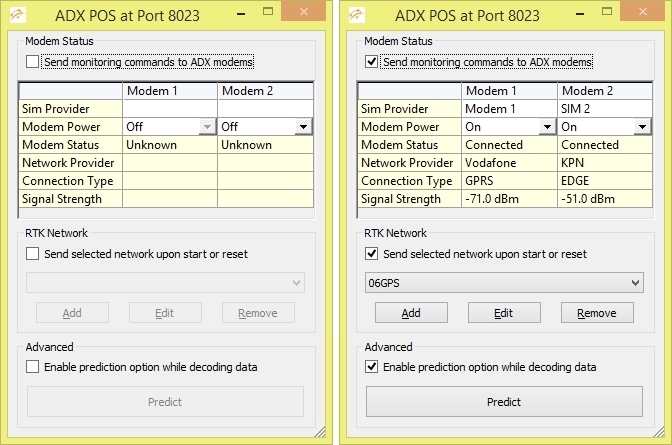
Modem Status
Enable "Send monitoring commands to ADX modems" in order to use the driver in active mode.
Enter names for the Sim providers (for reference) and set the power to on or off for each modem.
If the ADX dual modem sends a valid status reply messages, the dialog will show the status of each modem. In case no reply is received, the status will be set to "Unknown".
If a status is "Connected", the network provider name (from the MobileNetworkProviders.xml file), the connection access type and the signal strength in dBm is also displayed.
RTK Network
Enable "Send selected network upon start or reset" in order to change the dual modem network configuration.
With at least one RTK network defined, a network configuration setup can be selected from the dropdown list.
Click Add to open the Setup RTK Network dialog, where you can enter the settings for the RTK Network or Linqup Server. You can also Edit or Remove an RTK network entry.
The RTK network configuration settings are saved to (and next time loaded from) the AdxRtkSettings.xml file located in the '<Program Files>\QPS\Qinsy 8.1\XML\Driver' folder.
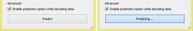
Advanced Predict Option
Tick "Enable prediction option while decoding data" in order to use the prediction option as implemented in the AD Navigation DC-Series driver.
As soon as this button is pressed, an extra value will be added to the decoded position computation mode. This offset value is by default set to 100.
Note that the solution mode can be monitored using a Positioning System Display or Generic Display (as RAW DATA, Positioning item Solution Mode).
With this option, a user can use the solution threshold in the Computation Settings to start predicting when the solution exceeds a user-defined value. Now, when sailing, the user may press the Predict button, just prior to going under a bridge, so Qinsy will start predicting immediately. When sailing away from the bridge, when the RTK solution improves again, the user may release the Predict button.
An advanced user may change the default offset value of 100 by modifying registry key 'Qinsy_Offset' under 'HKEY_CURRENT_USER\Software\QPS\Qinsy\8.0\Drivers\DrvQPSTerminatedUITCP\<System Name>\Settings'. When this value is set to zero, then the button will be disabled in the driver's dialog. Further, the default button labels "Predict" and "Predicting..." may also be changed by modifying registry keys 'Qinsy_Label_Off' and 'Qinsy_Label_On' under 'HKEY_CURRENT_USER\Software\QPS\Qinsy\8.0\Drivers\DrvQPSTerminatedUITCP\<System Name>\Settings'.