Description
Driver to decode the Navitronic Multi-channel Echosounder.
The system consist of a DPP 2000 Controller, which handles up to ten MCS 2000 Units. Each unit can have 6 channels, #1..#6 (read: transducer).
The DPP 2000 outputs for each channel the range measurement from the transducer head to the riverbed or from water level to the riverbed. This is a setting on the DPP Controller!
The DPP Controller may operate in Full Sync or in Group Sync mode. The driver will auto detect the mode.
In Full Sync mode all transducers will send a ping at the same time, all ping-times will be the same.
In Group Sync mode the transducers will alternately ping, so first all MCS 2000 units channel #1's will transmit a ping, after a return is received all channels #2 will send a ping and so on.
This mode will result in a different latency value for each group.
Driver Information
|
Driver |
Navitronic (DPP 2000) |
Interface Type |
- |
Driver Class Type |
Terminated |
|---|---|---|---|---|---|
|
No |
Input / Output |
Input |
Executable |
DrvNavitronic.exe |
|
|
Related Systems |
|||||
|
Related Pages |
|
||||
Decoding Notes
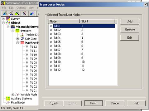
A variable number of channels can be decoded depending on the number of Transducer Nodes defined. The driver interpretates the slot id as the position in the output string. For instance if slot is 1 then the first position is decoded, 2 second, 3 third etc.
The ping time for each transducer is determined by taking the arrival time of the first character of the serial message and decrement it with the decoded latency.
Depth found in string position 1,7,13,18 etc are all part of group 1, the first latency value applies here, depths found on position 4, 10, 16 etc. are all part of group 4 and the fourth latency figure found in the string applies here.
Quality indicator is always decoded.
Interfacing Notes
Only a one-way interfacing cable is required for this driver.
Database Setup
All the transducer nodes must be defined as variable nodes on the vessel. These can be assigned to the system on the last page of the multi-transducer system wizard.
The slot numbers are the locations of the depth soundings in the string. Normally the port side most transducer is number 1.