
Description
Driver to decode the output data telegram from a MikroDigger Depth Control System XC1 device (manufacturer MIKROFYN A/S, Denmark).
The format is also supported by two other systems:
-
XC2 (you will need to install an older software version)
-
iCP31
The company was originally called Mikrofyn. In 2006, the company was sold to the Swedish Hexagon Group and is now part of Leica Geosystems.
References::
-
Website: leica-geosystems excavators
-
You-tube channel: Leica Geosystems Machine Control
This device can be found on excavators, cranes, diggers, etc. and consists of a main display unit and several inclination sensors.
These sensor are mounted on the boom, the stick and the bucket in order to measure its angle (pitch).
The XC1 then calculates accurately the horizontal and vertical position of the bucket or grab.
The position and the angle measurements can be outputted as an ASCII datastring to a serial device (read Qinsy).
Driver Information
|
Driver |
Mikrofyn MikroDigger |
Interface Type |
Serial |
Driver Class Type |
Terminated |
|---|---|---|---|---|---|
|
No |
Input / Output |
Input |
Executable |
DrvQPSTerminated.exe MIKRODIGGER |
|
|
Related Systems |
|
||||
|
Related Pages |
|
||||

Coding Notes
Decoding Notes
The driver automatically detects the outputted telegram format.
It is recommended to use the extended data telegram, so the XC1 needs to be instructed to send this telegram by a command.
System Interfacing
Interfacing Notes
XC2
For this system you could send one of the commands once.
For this you will need to use a straight serial cable:
-
DB9 male connector for the XC2;
-
DB9 female connector for the PC.
iCP31
This system can't be programmed. It needs to be triggered constantly (10Hz for example).
Interfacing takes place with a straight serial split cable:
-
DB9 male connector for the XC2
-
DB9 female connector for the PC → Qinsy Output system (from PC pin 3 Tx to iCP31 pin 3 Rx)
-
DB9 female connector for the PC → to Qinsy driver "Mikrofyn Mikrodigger" (from iCP31 pin2 Tx to PC pin 2 Rx)
Might be possible to split the comport on the PC as well using Virtual Posts software.
Trigger commands
The default baud rate settings, from the XC1 technical documentation, are 38400, 8, 1, none.
Output from Qinsy
We have seen that you need to send an output from Qinsy in order to get an output from the system.
You should be able to use the following drivers to get several message types:
|
Message type |
Message |
Generic output Driver |
|---|---|---|
|
Normal, short message |
1E 08 00 7D 00 00 28 23 01 01 10 |
|
|
Extended message (Recommended) |
1E 08 00 7D 00 00 28 23 03 01 0E |
|
|
Extra extended message |
1E 08 00 7D 04 00 28 23 07 01 06 |
Contact the Support department |
For more info on interfacing we suggest to contact Leica.
Qinsy Config
Database Setup
-
In order to decode the calculated bucket position, add a USBL System to your template database setup, and select driver "MIKROFYN MikroDigger (Bucket)".
Important:
The Transducer and the Reference Node on the 2nd page of the system wizard must be the GPS Antenna node.
Further, make sure that the setting "Correction Already Applied to Data Heading" is set to "None".
The setting "Sign Convention for Z Data" must be set to "Positive upward (height)".
On the last wizard page, select for the USBL Target the node that represents the bucket tip, located on the bucket object.
For this system the fields "VERT" and "HORI" are decoded. These fields are available in all three telegram messages. -
In order to decode the heading of the crane (machine), add a Gyro and Compass System to your template and select the driver "MIKROFYN MikroDigger (Heading)".
Important:
The Slot number on the next page of the system wizard must be "MHEAD", in capitals.
For this system the field "MHEAD" is decoded. Notice that this field is not part of the "Drill Software Data Telegram from XC1" message. -
In order to decode the (pitch) angles of the boom(s), the stick, and the bucket, add a Pitch, Roll and Heave Sensor System to your template and select the driver "MIKROFYN MikroDigger (Roll-Pitch) (Pitch)".
Important:
The Slot number on the next page of the system wizard depends on for which object you want the angle decoded. You may select "BOOM1", "BOOM2", "STICK" or "BUCKET", all in capitals.
For this system the fields "BOOM1", "BOOM2", "STICK" and "BUCKET" are decoded as pitch observation. These fields are only available in the "Extended Data Telegram from XC1" message. -
In order to decode the roll and pitch of the crane (machine), add a Pitch, Roll and Heave Sensor System to your template and select the driver "MIKROFYN MikroDigger (Roll-Pitch) (Pitch)".
Important:
The Slot number on the next page of the system wizard must be "MACHINE", in capitals.
For this system the fields "PITCH" and "ROLL" are decoded as a pitch/roll observation. Notice that these fields are not part of the "Drill Software Data Telegram from XC1" message. -
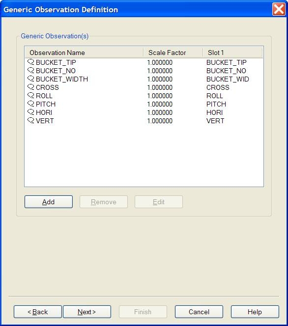
Other fields from the telegram may be decoded as generic observations, for displaying or analyzing purposes. Add a Miscellaneous System to your template and select driver "MIKROFYN MikroDigger".
On the next wizard page, add for each field you want to decode a generic observation.
Important:
The Slot Id must be in capitals, and the same as the field identifier as described in the telegram formats. E.g. use Slot "CROSS" in order to decode the Cross slope angle from the "Extended Data Telegram from XC1" message.
|
|
|
SLOT ID RESUMÉ |
|---|---|---|
|
System |
Description |
Slot Id |
|
USBL |
Decoding the vertical distance from GPS Antenna to the bucket tip as USBL dZ observation.
|
not required |
|
Pitch, Roll and Heave Sensor |
Decoding the pitch and the roll for the crane (machine) |
MACHINE |
|
Pitch, Roll and Heave Sensor |
Decoding the angle of the first boom, as pitch observation |
BOOM1 |
|
Pitch, Roll and Heave Sensor |
Decoding the angle of the second boom, if present, as pitch observation |
BOOM2 |
|
Pitch, Roll and Heave Sensor |
Decoding the angle of the stick, as pitch observation |
STICK |
|
Pitch, Roll and Heave Sensor |
Decoding the angle of the bucket, as pitch observation |
BUCKET |
|
Gyro and Compass |
Decoding the heading of the crane (machine), as heading observation |
MHEAD |
|
Miscellaneous |
Decoding each field individually as generic observation |
VERT
|
The I/O Interface parameters must be the same as for all the systems defined above.
Additional Info
Drivers IO Notes
Command line parameter description for "drivers.io" file. Please do not edit this drivers.io file, or only after contacting the QPS Support department.
Command line 'MIKRODIGGER' tells the driver to expect data from a MikroDigger XC1 unit.
Additional Information
References: leica-geosystems excavators
The company, originally called Mikrofyn, is now part of the large, Swedish-owned group, Leica Geosystems.
In 2006, the company was sold to the Swedish Hexagon Group.