Manual Touchdown Point Calculation - 02
Description
This driver is used to calculate the touchdown position of a pipe during pipe laying operations.
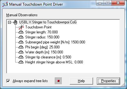
The user will need to enter various physical parameters like the stinger angle, pipe properties and depth.
From these values the built-in algorithm will calculate the relative depth and horizontal range with respect to the selected 'At' node on the barge.
The result of the calculation will be available as a USBL XYZ position offset: X coordinate will always be zero, Y will always be negative, Z will be negative down.
The status light in the bottom pane of the driver will blink green every second to indicate that a new calculation has been carried out.
Note that when the entered parameters are invalid the calculation can not be finished and the light will not blink.
For the calculation of the pipe laying barge track this system can be selected in the Controller's Session Setup wizard.

Driver Information
Driver | # Manual Touchdown Point Calculation | Interface Type | Driver Class Type | Manual | |
|---|---|---|---|---|---|
No | Input / Output | Input | Executable | DrvManualLayback.exe | |
Related Systems |
| ||||
Related Pages | |||||
Database Setup
The Manual Layback Driver is added to the database by adding a new USBL system to the survey vessel. The System definition user interface will be launched.
Type in system "Name" and select type "USBL System". Select I/O parameters driver "# Manual Touchdown point Calculation". Click Next.
Select in Location - Object the pipe barge and in the Location - Transducer combo box the node on the barge from which the calculation is started (stinger).
Select the "Sign convention for Z data" to be "Positive Upward (height)", note that this is not the default. Click Next.
Select Standard Deviations. Click Next.
Select under "USBL Targets" the object node that will represent the touchdown point.
Online
When in Qinsy Console the Online Controller is launched the Manual Layback Driver will automatically show up.
Click Properties in Manual Layback Driver user interface to edit the parameters: Stinger length / Stinger radius / Submerged pipe weight / Phi begin / Water depth / Stinger tip clearance / Height stinger above MSL.
Rotation reference: Select the system in the Computation Settings dialog of the Controller and select what reference bearing will be used by the computation to calculate the grid position for the 'To' node.
For pipe laying operations select the heading of the barge.
