
Description
This driver can be used to read the status of up to three toggle switches, push button switches, or relays via the serial port handshake lines.
The driver monitors the handshake lines and if a switch change is detected an observation is generated. On top of that every second the status of the switches is read in order to get a continuously updating observation.
The switches that are used should be of type on-on, that is it should have three contacts; the center contact makes a connection to either outer contacts. So a switch with only two contacts is not suitable!
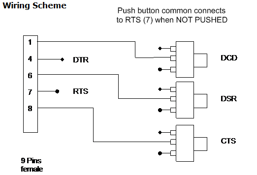
It is possible to create your own status switch box with the wire scheme below.
Typical usage of this box is for cranes that are utilized for dredging operations. The operator can press a switch to excavate the sounding grid or to perform a backfill on the grid.
When the electrical scheme as presented below is implemented the the flag observation will be '0' when not pushed and become '1' when pushed. The behavior of the flag observation can be inverted by adding a minus sign ('-) in front of the slot string.
When inverted the observation will be '1' when not pushed and '0' when pushed.
Use the slot to indicate which pins on the serial port are to be used.
Possible slots are:
-
CTS
-
DSR
-
DCD
-
-CTS (inverted action)
-
-DSR (inverted action)
-
-DCD (inverted action)
Driver Information
|
Driver |
Manual Switch (serial port) |
Interface Type |
Serial |
Driver Class Type |
|
|---|---|---|---|---|---|
|
No |
Input / Output |
Input |
Executable |
DrvStatusSerial.exe |
|
|
Related Systems |
|||||
|
Related Pages |
|
||||
Interfacing Notes
Note: The TX and Rx lines are not used, only the handshake lines are used.
The DTR line is set to disabled by the driver, the RTS line to enabled.
So for example the DCD line will be connected by the switch to either the DTR (pin 4) or the RTS line(pin 7).
The observation will be 1 when the corresponding handshake line is connected by the switch to the RTS line and 0 when connected to the DTR line.
To PC
Female 9 pins connector
|
1 |
DCD Input |
|
4 |
DTR used as output |
|
5 |
GND |
|
6 |
DSR Input |
|
7 |
RTS used as output |
|
8 |
CTS input |
|
9 |
RI Input |
Database Setup
-
Add a new driver select system type "Dredging Sensor".
-
Select driver "Manual Switch (serial port)".
-
Select appropriate COM port and other settings.
-
Click "Next"
-
-
to define the observations;
-
add an observation for every switch.
-
Add an observation type "Flag" and the location.
-
Don not forget to enter the Slot string to identify which handshake line the switch is connected to.
Possible Slots:-
DCD switch connected to pin 1.
-
DSR switch connected to pin 6.
-
CTS switch connected to pin 8.
The slot strings are case sensitive and should be in capitals.
Add a minus sign in front of the Slot to invert the observation flag. -
-
Grab Dredging Triggers:
Backfill will be carried out when the selected observation is non-zero.
Grab will be considered open when observation is zon-zero and closed when it is zero.
So a change in grab flag from '1' to '0' will invoke an excavation in the sounding grid whereas a flag change from '0' to '1' will invoke a dump on the sounding grid.