
Description
Driver to decode laser data from up to four SICK LMS200 scanners, all connected to one E-collector box, which is manufactured by Terra Vermessung AG.
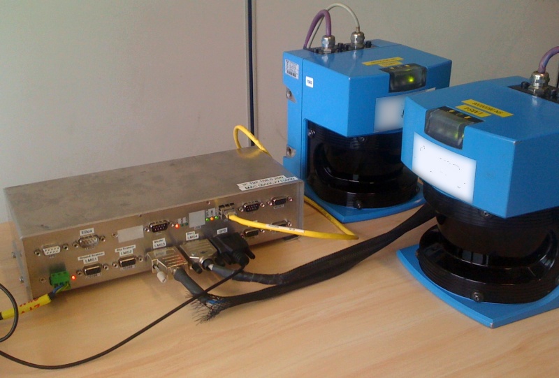
Instead of Qinsy being interfaced to each scanner separately via serial COMports and cables, you only need one network interface connection to this E-collector box.
Other advantages of this box are that it:
-
converts the serial (RS422) data stream from up to four scanners to one UDP network stream
-
synchronizes the scanners, in order to prevent interference between the scanners
-
accurately timestamps the scanner data using a PPS pulse from an external GPS receiver
Notice that the driver has user-interface in order to control the laser unit system, which can be found in the Controller's Echosounder Settings dialog.
Notes
-
Driver can not be used to interface directly to an LMS200 scanner.
You need to use a so-called E-collector box in between. -
Driver does decode range/angle values, but no reflectivity (or intensity, or remission).
Driver Information
|
Driver |
SICK LMS200 (E-collector Box) (XML) |
Interface Type |
Freebase/TCP/IP/UDP |
Driver Class Type |
Freebase |
|---|---|---|---|---|---|
|
Yes |
Input / Output |
Input/Output |
Executable |
DrvLaser.exe EBOX_LMS200 |
|
|
Related Systems |
|||||
|
Related Pages |
|
||||
Decoding Notes
Data is always broadcast via UDP network. It is advisable to use a fast (at least 100Mb) network card, due to the enormous amount of data to be expected. Communication with the device is based on a full-duplex UDP connection.
The driver is configured as a Multibeam System and creates range/angle 'multibeam' observations.
('multibeam' versus 'laser scanning'-terminology: ping = scan (i.e. 360° around), footprint = pixel = pulse, swath = line)
The number of beams (pixels) depends on the on-line used settings, like (user-definable) range mask (see also Online Setup below).
For each connected LMS200 scanner you may expect the following data statistics:
-
The maximum expected number of beams per scan is 181.
-
The maximum expected number of beams per second is 13500.
-
The number of scans per second (full head rotations) will be 75 Hz
-
The maximum field of view is 180°
Qinsy will be updated with the decoded data after each full rotation of the laser head.
Upon decoding, the measured range is calculated to a travel time, using the speed of light as a constant.
Database Setup
-
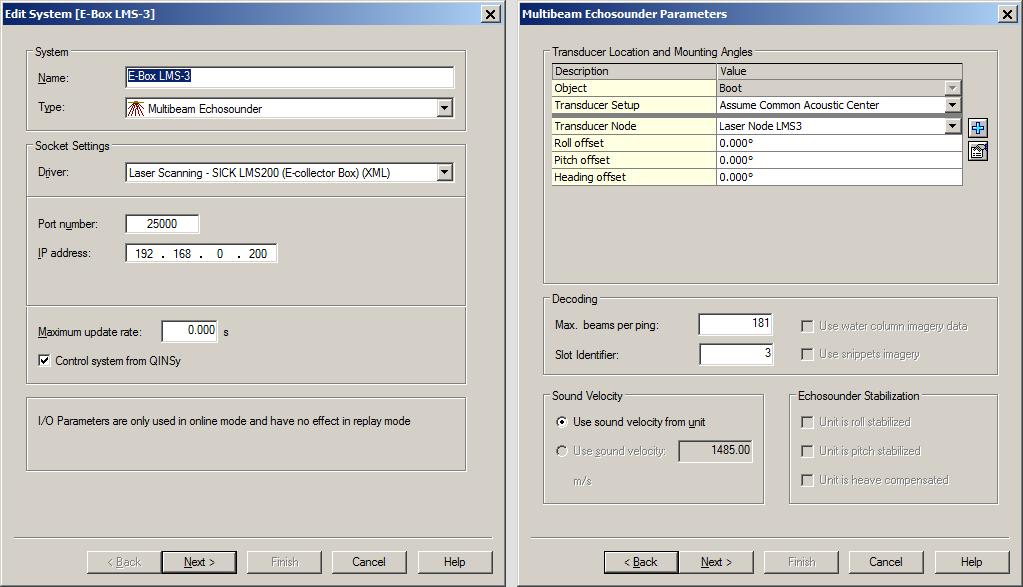
Add a Multibeam Echosounder system to your template setup, and select driver "Laser Scanning - SICK LMS200 (E-collector Box) (XML)".
The Port number must be the same as the LAN port of the E-collector box, normally 25000. The driver will communicate (sending and receiving commands) via this configuration port of the scanner.
Important is to enter for the IP Address the address of the scanner, e.g. 192.168.0.200, but the exact value should be provided by the manufacturer of the box.
The maximum update rate can be used, but it is recommended to leave it at zero . In that way it is most likely that the scanner's update rate of 75 Hz will be achieved.
The setting Control system from Qinsy must be enabled for the first defined laser scanning system. Do not enable this option for the others.
This setting enabled will make sure that you can control the scanner(s) via the E-collector box using the Controller while online. See below under Online Setup for the details. -
On the next page, the Transducer Location, the Mounting Angles and the Slot Identifier are important:
As a rule of thumb, when you mount the unit backwards on your vehicle with face down for scanning profiles, then you may leave all offsets (Roll/Pitch/Heading) zero in the template setup.
A scanned profile as seen in a Raw Multibeam display should then be as in the real world.
Set the Max. beams per ping value to 181. The actual number of beams will be variable and depends for example on the used settings on-line and on the targets being scanned.
The Slot Identifier should be a number between 1 and 4, in the same order as connected on the E-Collector box -
Leave all other values on the next page(s) also at their defaults.
Online
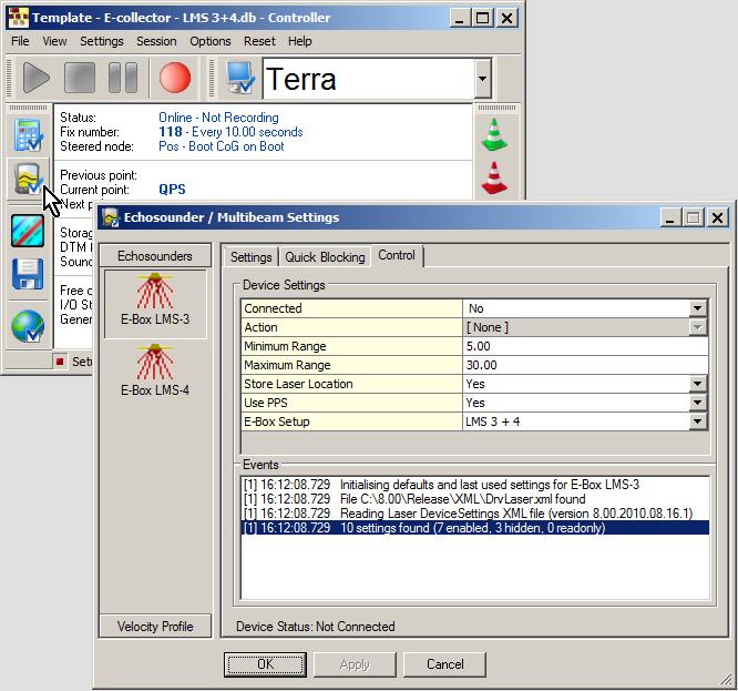
When on-line, the laser unit can be controlled using the Controller:
Select Echosounder Settings, click on the Laser System icon, and select the 'Control' tab page.
|
Connected |
In order to communicate with the scanner(s) via the E-collector box, you must make a network connection first.
|
|
Action |
Selected action will be sent to the E-collector box, immediately after hitting the Apply or OK button. You must be connected first in order to select an action.
|
|
Scan Mode |
Select the required measurement method
|
|
Minimum Range |
Set the minimum required range in meters. Valid values: 0 to 80 meters.
|
|
Maximum Range |
Set the maximum allowed range in meters. Valid values: 0 to 80 meters.
|
|
Store Laser Location |
If enabled, an additional pixel with zero co-ordinates will be added to each line scan, in order to indicate the exact laser scanner location in the resulting point cloud. This extra pixel will always have beam number 1, and its intensity/quality value will be zero. |
|
Use PPS |
This setting is highly recommended, in order to use exact time stamping of the laser data.
|
|
E-Box Setup |
Use this setting to inform the driver which LMS200 laser scanners are connected to the E-collector box.
|
|
Capture Raw Data |
Enable this option if you want to store the raw binary data stream coming straight from the unit to a log file on disk.
|
Generic Display
A generic display can be used to show the numerical values for the number of beams (pixels) being scanned per ping (line), the number of beams per second, the range values, etc.
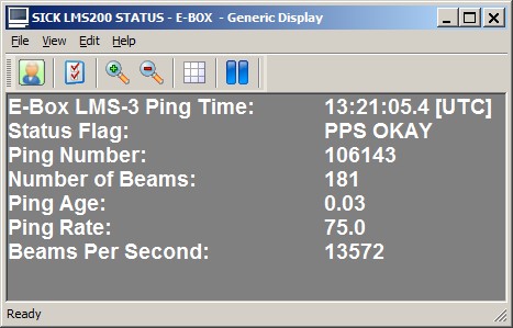
It is useful to check that the ping age value is a small value, it should be around zero, e.g. 0.03 or 0.02.
Also important, make sure that the Status Flag value is 2, meaning 'PPS OKAY', when the option 'Use PPS' is enabled.
You may use the attached example Generic Display Layout file as example: Copy this layout (Use 'Save Link As...') to your current Project's Settings\Display folder and open it using a new Generic Display. You only have to select the correct laser system as defined in your template setup.
If you experience problems using your laser scanner in combination with this driver or if you need additional information or support then please attach the daily laser log-file when submitting your JIRA support ticket.
At the bottom of this section you'll find the information on where to find this daily laser log file
Network Problems
Windows Firewall
A commonly reported problem is that network data is blocked by the Windows Firewall.
When this happens you may see that data does come in using other utilities (like the I/O Tester or the manufacturer's own software), but that the Qinsy driver does not accept any data.
The following (Windows 10) steps may solve this:
-
Go offline, open the PC Settings (Start menu, Settings)
-
Select Windows Firewall (Privacy & security, Windows Security, Firewall & network protection)
-
Select Advanced settings
-
Select Inbound Rules, highlight all 'Driver for Laser Scanning' entries and delete them using the right mouse popup menu (or Del key)
-
If you now go online, the Windows Security Alert message will pop up: now it is important to Allow access!
Multiple Network Cards
Another possible problem could be that your computer has more than one network card installed (e.g. LAN and WIFI) but within the same sub-net mask range (255.255.255.0).
It is recommended to make the first three digits unique for each network card IP address.
You may check the daily laser log-file; it will show the IP addresses for all available network adapters and indicates which one the driver will try to use automatically:
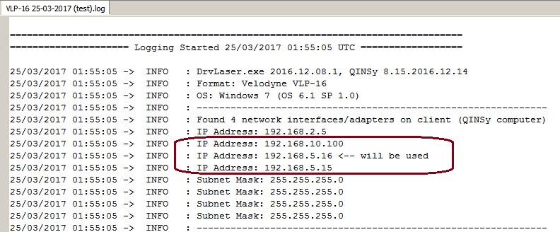
Please check that the driver is using the correct one!
Missing Data
If you occasionally experience gaps in your data, this may be caused by a general Windows setting that affects the data throughput of your network card.
Change the following registry key: HKEY_LOCAL_MACHINE\SOFTWARE\Microsoft\Windows NT\CurrentVersion\Multimedia\SystemProfile\NetworkThrottlingIndex
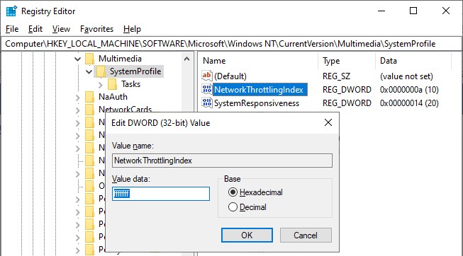
Set the new value to ffffffff (which will tell Windows to disable network throttling) and restart the computer.
Note that disabling network throttling may affect playing multimedia on your computer, but for laser scanning operations it is advisable to have a maximum data throughput of your network.
Daily Laser Log File
All user actions, system information and reported errors are logged in a daily laser log file which can be found in the current project's LogFiles subfolder.
The filename convention for this ASCII log-file is <System Name> DD-MM-YYYY.log, so every day there will be a new one.
Note that all time stamps in this log file are by default in UTC. An advanced user may change this to local time zone (LTZ) by changing the registry key:
HKEY_CURRENT_USER\Software\QPS\QINSy\8.0\Drivers\DrvLaser\Settings\TimeLogFileUtc value from 1 to 0.