
Description
Driver to control and decode data from a Renishaw Scanning Laser Module.
This SLM unit can be a stand alone system, or part of a Renishaw configuration, combining accurate GNSS, an INS and one or two Laser Scanning Heads, already fully calibrated for mounting angle offsets.
|
|
|
|
|
|
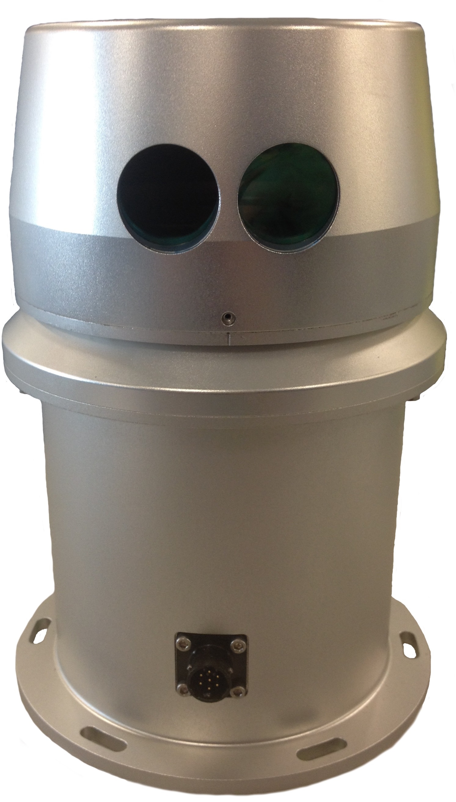
Stand alone SLM system |
|
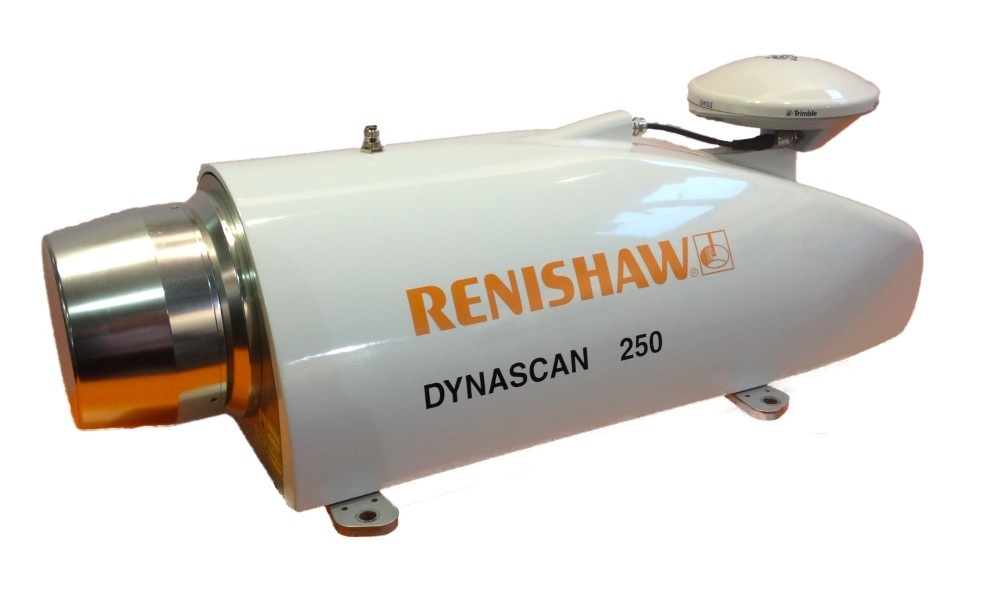
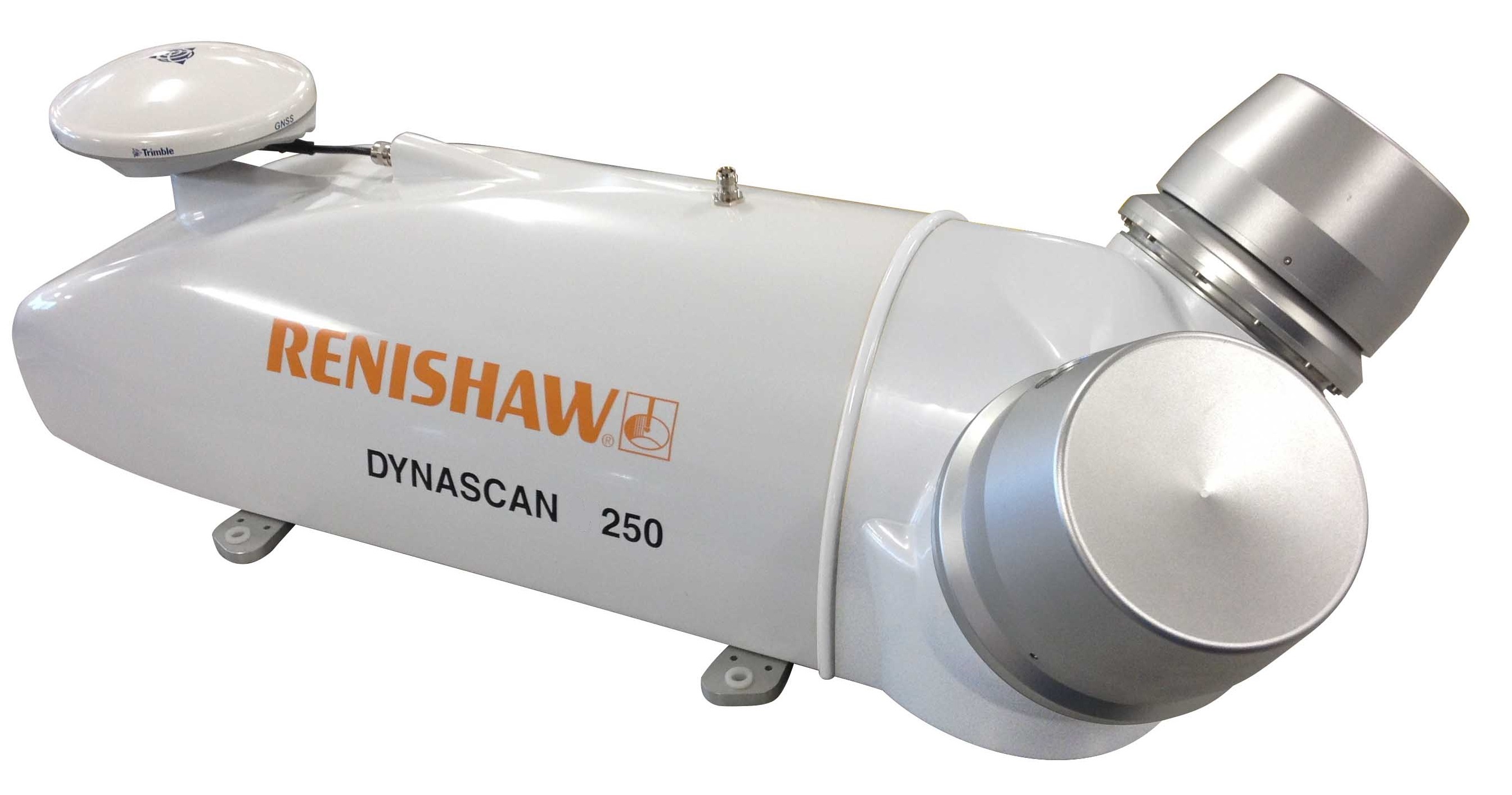
Dynascan configuration (single head and dual head) |
|
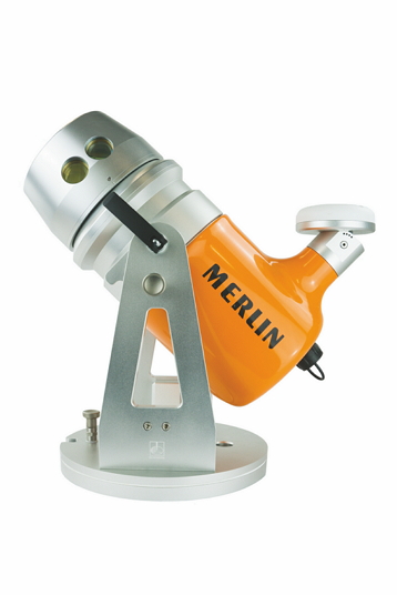
MERLIN – Time-tagged, vessel mountable, Lidar system |
Laser stands for L ight A mplification by S timulated E mission of R adiation. Laser class used by the LMS is 1 (FDA/IEC/EN60825-1), which is eye-safe, or 2 when the optional red pointer is available.
Notice that the driver has user-interface in order to control the laser unit system, which can be found in the Controller's Echosounder Settings dialog. For more information see Online setup below.
Driver Information
|
Driver |
Renishaw SLM (XML) |
Interface Type |
Freebase/UDP |
Driver Class Type |
Freebase |
|---|---|---|---|---|---|
|
Yes |
Input / Output |
Input and Output |
Executable |
DrvLaser.exe MDL_SLM |
|
|
Related Systems |
|||||
|
Related Pages |
|
||||
Decoding Notes
Communication between the driver and the SLM unit goes via a binary data stream, using Renishaw's own so-called SLM MDA072 format. This document does not describe the format description of these commands, messages and/or data packages.
Command messages to and data packets from the laser unit are broadcast via a UDP network connection.
This communication is based on a half-duplex UDP connection, which means that the driver is either in receive state, or in send state.
Due to the enormous amount of data to be expected, it is advisable to use a fast (at least 100Mb) network card. For more information see Network Setup below.
The driver will update Qinsy with the decoded data after each full rotation of the laser head.
Upon decoding, the measured range is transformed to a travel time, using the speed of light as a constant.
Next to the pixel range and angle value, one other important attribute is decoded: the signal strength from the target's surface.
This signal strength is decoded and stored as Intensity and Quality indicator:
-
I ntensity of the beam
The Intensity will be the signal strength and is expected to be in the range between 0 and 4095.
-
Q uality Indicator of the beam
The Quality Indicator is a so-called normalized Intensity and this figure is always in the range of 0-255. Therefore the signal strength is divided by 16 to make it fit.
|
INPUT |
|
|
|
|
|
|---|---|---|---|---|---|
|
File |
EXT |
Created |
PIXEL |
I ntensity [0 - 4049] |
Q uality [0-255] |
|
Qinsy Database - Replay |
*.DB |
Online |
Range/Angle |
|
|
|
P rocessing M anager - Validator |
*.QPD |
Online, Replay |
ENH (cm) |
|
|
|
(since 8.10.2013.01.24.1) |
*.QPD2 |
Online, Replay |
ENHIQ (cm) |
|
|
|
QLOUD |
*.PTS |
Online, Replay |
ENHIQ (cm) |
|
|
|
Sounding Grid |
*.GRD |
Online, Replay, PM |
ENH (cm) |
|
|
|
QLOUD |
*.QTM |
PM / QLOUD |
ENH (cm) |
|
|
The Intensity or Quality can be very useful to color-code the data using processing software like the Validator or QLOUD.
Notice that the original decoded value for the Intensity and Quality will be modified when the reported GPS Time/PPS pulse status is bad. For more information about this see Interfacing.
Interfacing Notes
Timing
By default, the driver will time-stamp the data when received at the UDP port.
When a full rotation is decoded, a delay time will be determined by dividing the rotation time (last arrival - first arrival) by the number of received packets. With this delay time, the arrival of each individual packet will be calculated.
However, due to UDP network characteristics in general, and because of latency inside the scanner, this will result in inaccurate timing.
Therefore timing via PPS/Time Synchronization pulse from GPS is highly recommended.
This means that your SLM unit must be interfaced with an external Time Synchronization pulse from a GPS receiver and a UTC time-tag message from the same GPS receiver. The required format of the time-tag message depends on the used GPS receiver, but normally this will be NMEA ZDA.
Notice that when working with a Dynascan system, Renishaw has already fully integrated GPS and PPS/Time Synchronization from factory.
It is important that Qinsy is also interfaced with a Time Synchronization system, so all systems will operate in the same time frame.
The SLM unit automatically informs the driver if something was wrong with the Time Synchronization pulse and/or UTC time-tag message.
As soon as the driver receives a bad status about Time Synchronization timing, it will modify the original decoded values for the Intensity and Quality as follows:
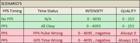
Because the quality will always be 0 or 255 during periods with bad timing, you can easily spot those areas inside the Validator or QLOUD:
Use for color-coding the Quality and set the color scale range somewhere between 0 and 255. The under- and overflow color (default red and blue) will now represent the areas with bad timing.
Network Setup
All communication to and from the SLM laser unit goes via the onboard LAN network.
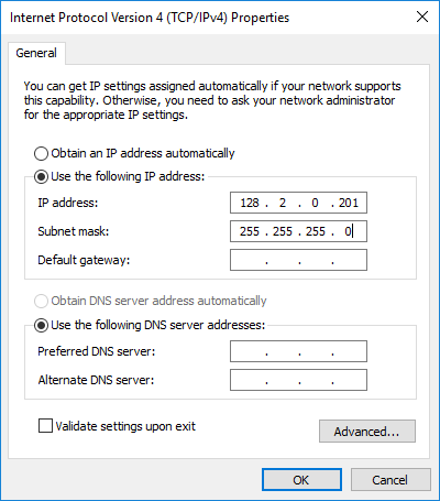
The exact LAN IP address of the laser unit should be provided by the manufacturer or your reseller. Normally Renishaw configures their SLM laser units with IP address 128.2.0.2xx.
The LAN IP address of your computer's network should be in the same range, except for the last digit.
This must be a unique number! Use for the subnet mask the values 255.255.255.0
-
Windows 7, 8.1 and 10:
Control Panel-Network and Sharing Center-Change adapter settings-Click right-mouse on Local Area Connection-Properties-Internet Protocol Version 4 (TCP/IPv4)-Properties...
Flowchart
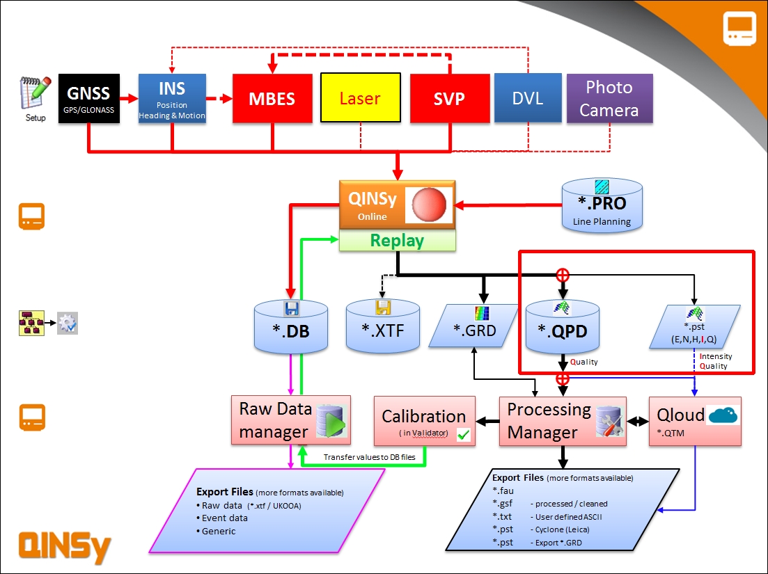
General flowchart laser scanning
Database Setup
The driver is treated internally as a multibeam system, creating multibeam 'range' and 'angle' observations, therefore you will find the laser system drivers under category type Multibeam Echosounders.
Terminology 'Multibeam' versus 'Laser scanning'
|
Multibeam |
Laser scanning |
|---|---|
|
Ping |
Scan (i.e. 360° around) |
|
Footprint or Beam |
Pixel or Pulse |
|
Swath |
Line or Scan |
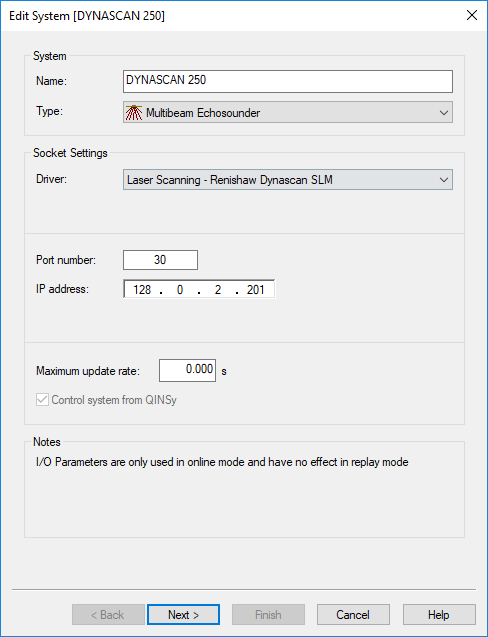
1. Edit System Wizard
Add a Multibeam Echosounder system to your template setup, and select driver "Laser Scanning - Renishaw Dynascan SLM".
-
The Port number must be the same as the configuration port of the scanner. The driver will communicate via this configuration port of the scanner. Ask the manufacturer or reseller what the exact port number should be. Normally it will be 30.
-
Also important is to enter the exact IP address of the scanner. Each scanner should have its own unique IP address. See Network Setup for more information.
-
Leave the maximum update rate at zero.
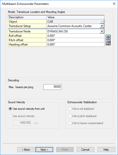
2. Multibeam Echosounder Parameters
Important are the Transducer Location (Node) and Mounting Angles (offsets) on the second wizard page.
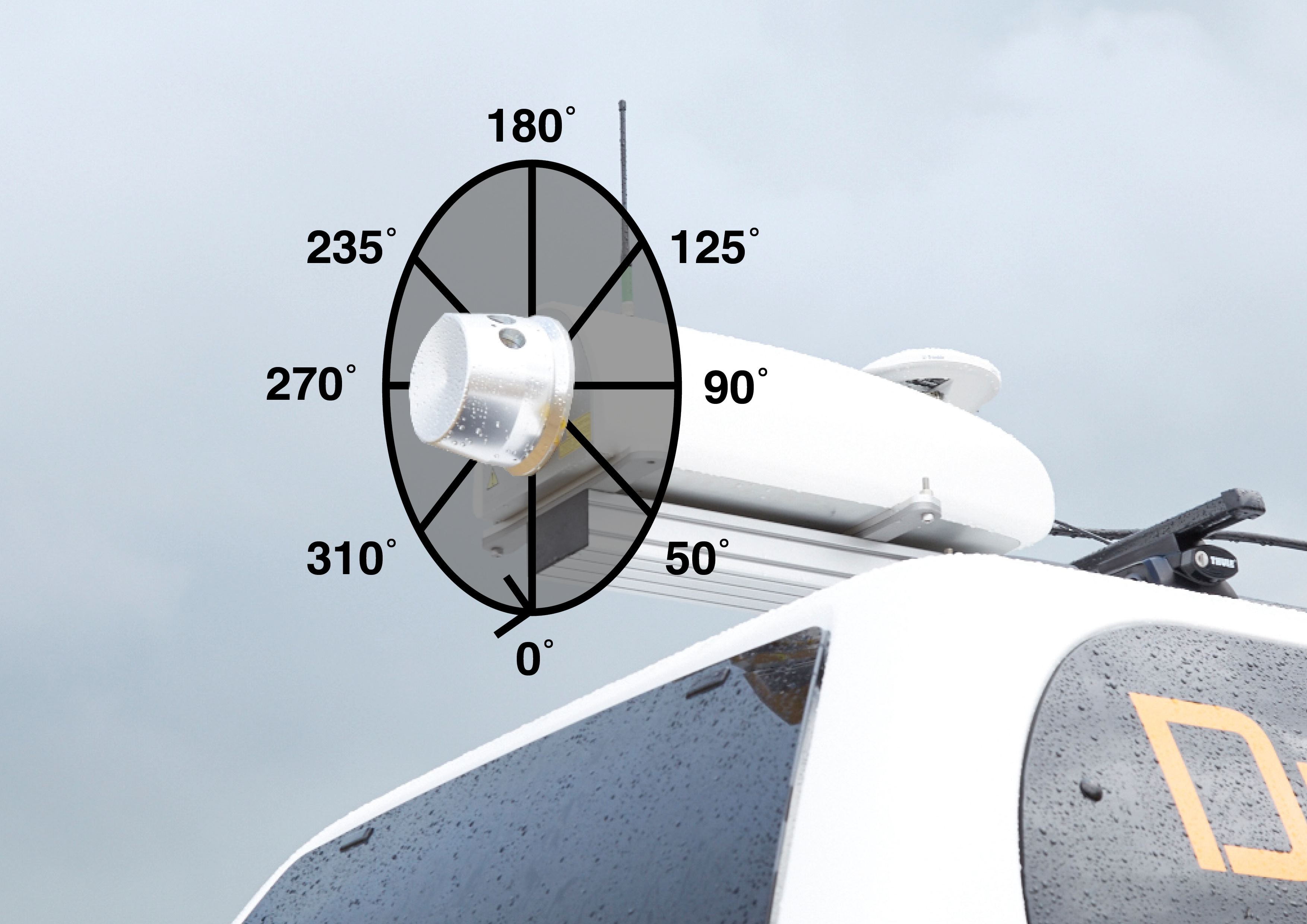
-
As a rule of thumb, when you mount the laser unit backwards on your moving vehicle, and the marker on the unit is pointing upwards, then you may leave the Roll, the Pitch and the Heading offset zero.
A scanned profile as seen in a Raw Multibeam display should then be as in the real world.
As another example, if you mount the scanner backward looking, but with the marker pointing downwards, then you should already enter a Roll offset of 180°.
-
Set the Max. beams per ping value to 36000.
The actual number of beams will be variable, and depends for example on the used on-line settings and on the targets being scanned.
3. Echosounder Accuracy Parameters
-
You may leave all values on the third wizard page at their defaults.
4. Multibeam Echosounder Corrections
Important are the Range and Beam Angle Corrections on the last wizard page. These C-O settings are specific for Renishaw SLM laser units and can be measured by factory calibration, or determined after a calibration run.
-
Range Correction is the correction on the measured raw laser range. It can optionally be enabled if required, for Renishaw SLM a single correction for the entire range is sufficient.
It consists of two figures: a C-O which is the offset on the range, this should always be entered in meters, and a Scale Factor.
This figure will be multiplied with the range once the C-O has been added to it.-
Note: that if the Scale Factor is not used then leave it at 1.0.
-
-
Beam angle C-O is the offset on the rotation of the head.
-
Tilt angle C-O is the angle the laser is tilted from the rotation plane.
Beam Angle & Tilt Angle
Please contact the manufacturer for more information related to the beam angle and tilt angle.
Online
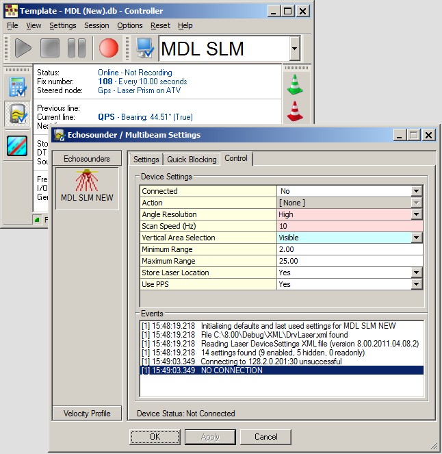
When on-line, the SLM laser unit can be controlled using the Controller.
Select Echosounder Settings, click on the Laser System icon, and select the 'Control' tab page:
|
Connected |
In order to communicate with the scanner, you must make a network connection first.
|
|
Action |
Selected action will be sent to the laser unit, immediately after hitting the Apply or OK button. You must be connected first in order to select an action.
|
|
Angle Resolution |
Set the angle resolution, i.e. the angle increment between two consecutive pixels.
|
|
Scan Speed (Hz) |
Enter the rotation speed of laser head. Valid values: 1 - 10 Hz.
|
|
Vertical Area Selection |
Scanner head rotates 360° every line at the selected scan speed.
|
|
Minimum Intensity |
Set the minimum required intensity (signal strength). Valid values: 0 to 4095.
|
|
Maximum Intensity |
Set the maximum allowed intensity (signal strength). Valid values: 0 to 4095.
|
|
Minimum Range |
Set the minimum required range in meters. Valid values: 0 to 500 meters.
|
|
Maximum Range |
Set the maximum allowed range in meters. Valid values: 0 to 500 meters.
|
|
Store Laser Location |
If enabled, an additional pixel with zero range will be added to each line scan, in order to indicate the exact laser scanner location in the resulting point cloud. This extra pixel will always have beam number 0, and its intensity and quality values will be zero. |
|
Use PPS |
This setting is highly recommended, in order to use exact time stamping of the laser data.
|
|
Capture Raw Data |
Enable this option if you want to store the raw binary data stream coming straight from the unit to a log file on disk.
|
Additional Information
The SLM has the following features and limitations:
-
The range resolution will be centimeters, with a maximum of 150 meters (500 feet), or 500 meters (1500 feet).
-
The angle resolution will be 0.1° or 0.01° (user-definable).
-
The number of scans per second will be between 1 and 10 Hz. (user-definable)
Newer SLM units may support rotation speeds of up to 20 Hz.
We have seen that it shuts down when you go above a certain spin-rate. In that case check if you have a sufficient power supply.
-
The maximum expected number of beams (pixels) per second will be 36000 (theoretically).
-
The actual number of beams depends on the on-line used settings, like range mask, vertical angle mask, intensity mask, etc.
(see Online Setup for more information)
If you experience problems using your laser scanner in combination with this driver or if you need additional information or support then please attach the daily laser log-file when submitting your JIRA support ticket.
At the bottom of this section you'll find the information on where to find this daily laser log file
Network Problems
Windows Firewall
A commonly reported problem is that network data is blocked by the Windows Firewall.
When this happens you may see that data does come in using other utilities (like the I/O Tester or the manufacturer's own software), but that the Qinsy driver does not accept any data.
The following (Windows 10) steps may solve this:
-
Go offline, open the PC Settings (Start menu, Settings)
-
Select Windows Firewall (Privacy & security, Windows Security, Firewall & network protection)
-
Select Advanced settings
-
Select Inbound Rules, highlight all 'Driver for Laser Scanning' entries and delete them using the right mouse popup menu (or Del key)
-
If you now go online, the Windows Security Alert message will pop up: now it is important to Allow access!
Multiple Network Cards
Another possible problem could be that your computer has more than one network card installed (e.g. LAN and WIFI) but within the same sub-net mask range (255.255.255.0).
It is recommended to make the first three digits unique for each network card IP address.
You may check the daily laser log-file; it will show the IP addresses for all available network adapters and indicates which one the driver will try to use automatically:
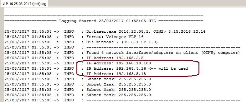
Please check that the driver is using the correct one!
Missing Data
If you occasionally experience gaps in your data, this may be caused by a general Windows setting that affects the data throughput of your network card.
Change the following registry key: HKEY_LOCAL_MACHINE\SOFTWARE\Microsoft\Windows NT\CurrentVersion\Multimedia\SystemProfile\NetworkThrottlingIndex
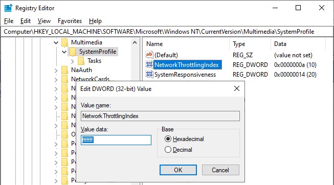
Set the new value to ffffffff (which will tell Windows to disable network throttling) and restart the computer.
Note that disabling network throttling may affect playing multimedia on your computer, but for laser scanning operations it is advisable to have a maximum data throughput of your network.
Daily Laser Log File
All user actions, system information and reported errors are logged in a daily laser log file which can be found in the current project's LogFiles subfolder.
The filename convention for this ASCII log-file is <System Name> DD-MM-YYYY.log, so every day there will be a new one.
Note that all time stamps in this log file are by default in UTC. An advanced user may change this to local time zone (LTZ) by changing the registry key:
HKEY_CURRENT_USER\Software\QPS\QINSy\8.0\Drivers\DrvLaser\Settings\TimeLogFileUtc value from 1 to 0.