
Description
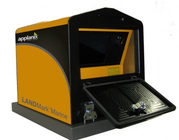
Driver to decode laser data from an Optech ILRIS-HD laser scanner, or from an Applanix LANDMark™ Marine, which combines an ILRIS-HD scanner with Applanix POS MV™ into a fully integrated marine vessel based mobile mapping solution.
Laser stands for L ight A mplification by S timulated E mission of R adiation. Laser class used by the ILRIS-HD is 1 or 1M (IEC 60825-1), which is eye-safe.
Driver Information
|
Driver |
Applanix LANDMark Marine (XML) |
Interface Type |
Freebase/TCP/IP |
Driver Class Type |
Freebase |
|---|---|---|---|---|---|
|
Yes |
Input / Output |
Input |
Executable |
DrvLaser.exe ILRIS |
|
|
Related Systems |
|
||||
|
Related Pages |
|
||||
Decoding Notes
Data is always broadcast via TCP network. It is advisable to use a fast (at least 100Mbit) network card, due to real-time scanning and the huge amount of data. Communication via the USB or serial interface is not supported.
The maximum expected number of beams per second for the ILRIS-HD is about 10 000 (ten thousand).
The actual raw data stream is Optech's proprietary format. This document does not describe this format.
Interfacing Notes
Timing
Due to network characteristics in general, and because of latency inside the scanner, time stamping upon arrival will result in inaccurate and variable timing. Therefore timing via a PPS Time Synchronization pulse from GPS is highly recommended.
This means that your laser unit must be interfaced to an external PPS pulse from a GPS receiver and a UTC time-tag message from the same GPS receiver.
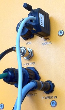
The required format of the time-tag message is a so-called $GPPPS message, an NMEA look-alike, which can be outputted by the Applanix POS MV™ unit. The time inside this message must be UTC and not GPS.
If you don't have an Applanix POS MV™ unit, you can output this message to the laser unit using output driver "Generic Output (User-defined ASCII)". Download generic layout GPPPS.xml (Use 'Save Link As...') and copy it to subfolder \Drivers\Definitions\Output of the Qinsy Program folder. Select this layout when going online for the first time using the Generic Output driver, which should be located in the Windows taskbar.
It is important that Qinsy is also interfaced to a PPS system, so all systems will operate in the same time frame.
Network Setup
All communication to and from the laser unit goes via the onboard LAN network, using the TCP protocol. It is not recommended to use a wireless network in case your unit is equipped with it, always use the wired one.
The exact LAN IP address of the laser unit should be provided by the manufacturer or your reseller. A typical wired IP address may look like this: 192.9.206.248.
The LAN IP address of your computer's network should be in the same range, except for the last digit. This must be a unique number! Use for the subnet mask the values 255.255.255.0
System Configuration
Most control of the laser unit must be done using ILRIS 3D PC Controller Software.
This document does not replace the ILRIS 3D PC Controller Software manual, but only emphasizes the important settings needed to collect laser data successfully with Qinsy.
SUMMARY: Enable Data Streaming and set GPS Logging to Dynamic
-
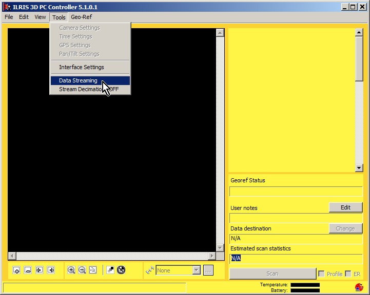
Start this program (preferably before going online with Qinsy) and enable Tools pull-down menu option 'Data Streaming'
Use the Message Window to confirm that the Data streaming server has been started: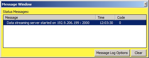
From this moment on you may go online with Qinsy and you should be able to connect to the data streaming server (see Online Setup settings above) -
Use File pull-down menu option Connect... to let the software connect to the laser unit:
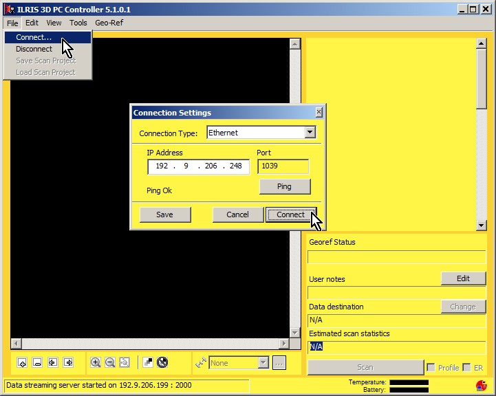
Remember that the laser unit should already be switched on for at least two minutes before connecting, in order to finish and settle its internal booting sequence.
Use the Message window to confirm that a successful connection has been established::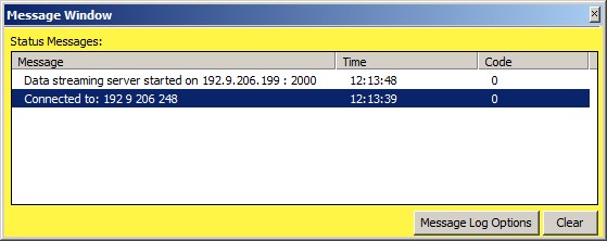
-
Last important setting: Always set the so-called GPS Logging option to Dynamic.
This will guarantee a correct time-stamping of the data, even when you are not using PPS for timing.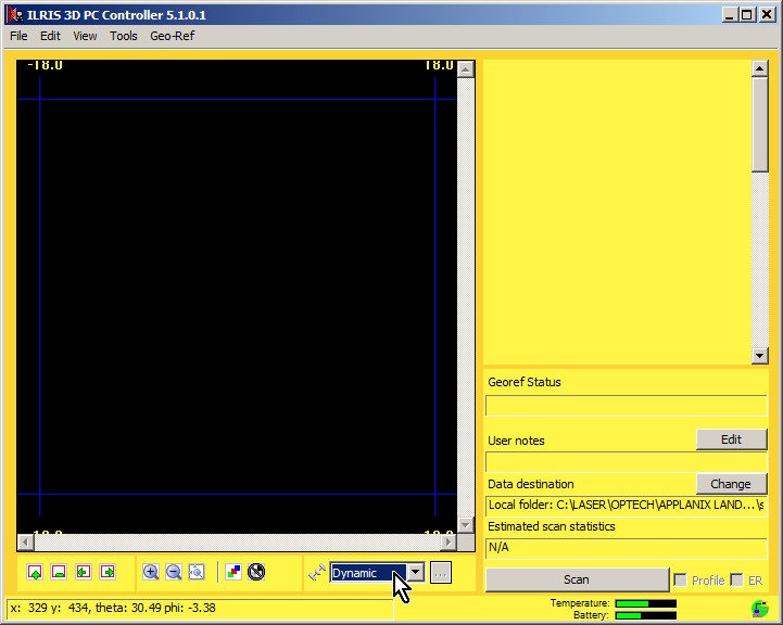
-
For using the scanner on a moving vehicle it is highly recommended to set the Scan Pattern to Line, Pattern Repeat to Continuous and Line Type to Vertical.
Please use the ILRIS 3D PC Controller Software user manual for further help on how to operate the scanner, like defining ROIs (Region of Interests), Camera Settings, Spacing, etc.
Database Setup
First, internally the driver is treated as a multibeam system, creating multibeam 'xyz' observations, therefore you will find the laser system drivers under category type Multibeam Echosounders.
('multibeam' versus 'laser scanning'-terminology: ping = scan (i.e. 1 vertical line scan), footprint = pixel = pulse, swath = line)
1. Edit System Wizard
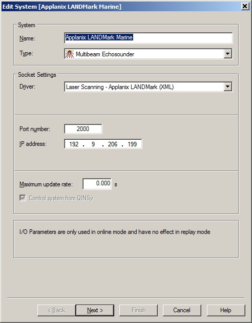
Add a Multibeam Echosounder system to your template setup, and select from the list driver "Laser Scanning - Applanix LANDMark Marine (XML)" or "Laser Scanning - Optech ILRIS-HD (XML)". Notice that both drivers are the same.
-
The Port number should be 2000. The driver will communicate via this configuration port with the ILRIS 3D PC Controller software. You may ask the manufacturer or reseller what the exact port number should be. Normally it will be 2000.
-
It is important to enter the IP Address of the computer that runs the ILRIS PC Controller software, so this is most likely the Qinsy computer. This is because the driver does not actually make a connection with the laser unit itself, but with the data streaming server that is started within the ILRIS 3D PC Controller software (see also this chapter).
-
Leave the maximum update rate at zero.
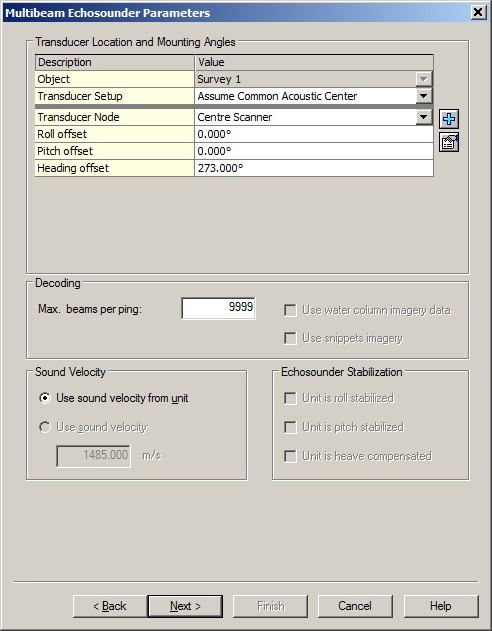
2. Multibeam Echosounder Parameters
Important are the Transducer Location (Node) and Mounting Angles (offsets) on the second wizard page.
-
As a rule of thumb, when you mount the laser unit forward on your moving vehicle (which is not a good idea), so the face (scan area) of the unit is pointing forward, then you may leave the Roll, the Pitch and the Heading offset zero. A scanned profile as seen in a Raw Multibeam display should then be as in the real world. Normally on moving vehicles the scanner will be mounted either to port or starboard side. In that case you should set the heading offset to respectively 270 or 90°.
-
Leave the Max. beams per ping value to 9999.
The actual number of beams will be variable, and depends for example on the used on-line settings and on the targets being scanned.
3. Echosounder Accuracy Parameters
-
You may leave all values on the third wizard page at their defaults.
4. Multibeam Echosounder Corrections
-
You may leave all values on the last wizard page at their defaults.
Online
Most control of the laser unit (like start/stop scanning, defining scan areas and resolution) should be done using ILRIS 3D PC Controller Software . See the chapter below for detailed information about the necessary settings of this external software package.
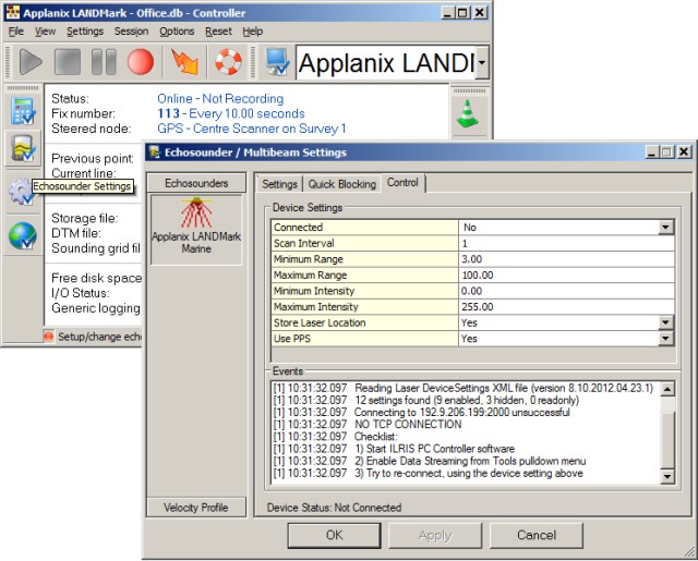
Some additional control that is required can be done using the Qinsy Controller:
Select Echosounder Settings, click on the Laser System icon, and select the 'Control' tab page.
|
Control |
Device Settings |
|---|---|
|
Connected |
In order to communicate with the scanner, you must make a network connection first.
|
|
Scan Interval |
Leave this value at 1, in order to receive all scans that belong to the selected scan spacing. However if you wish to decrease the resulting ping rate, you may want to set a value in order to use every nth scan.
|
|
Minimum Range |
Set the minimum required range in meters. Valid values: 0 to 1800 meters.
|
|
Maximum Range |
Set the maximum allowed range in meters. Valid values: 0 to 1800 meters.
|
|
Minimum Intensity |
Set the minimum required (scaled) intensity. Valid values: 0 to 255.
|
|
Maximum Intensity |
Set the maximum allowed (scaled) intensity. Valid values: 0 to 255.
|
|
Store Laser Location |
If enabled, an additional pixel with zero xyz will be added to each line scan, in order to indicate the exact laser scanner location in the resulting point cloud. This extra pixel will always have beam number 0, and its intensity and quality value will be zero. |
|
Use PPS |
This setting is highly recommended, in order to use exact timestamping of the laser data.
|
|
Latency |
Enter a fixed latency value in milliseconds. The time will be corrected by subtracting this value.
|
|
Capture Raw Data |
Enable this option if you want to store the raw binary data stream coming straight from the unit to a log file on disk.
|
Generic Display
The Generic Display can be used to show the numerical values for the number of beams (pixels) being scanned per ping (scan), the number of beams being scanned per second, the ping rate (scan rate in Hz), range values, etc.
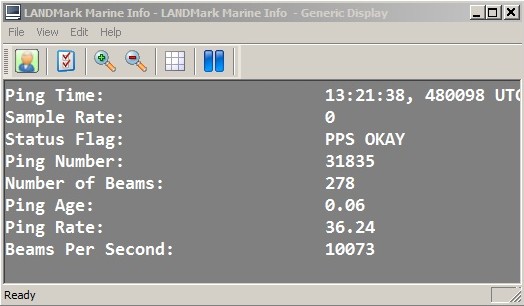
Important value to monitor is the Ping Age, especially when setting 'Use PPS' is enabled. This value should be small, around zero.
Notice that PPS pulse and time tag ($GPPPS) is interfaced to the laser unit, but there is no feedback whether the unit has accepted pulse and timetag.
For example, if you see a very large Ping Age value (+tive or -tive), then this is a severe indication that the initial timing inside the laser unit is wrong.
Another scenario may be a Ping Age around 15 a 16 seconds. This is an indication that the time from the $GPPPS message is GPS time, instead of the required UTC time.
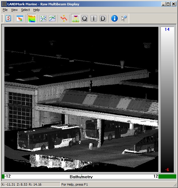
Raw Multibeam Display
A Raw Multibeam Display in waterfall scrolling mode is ideal for real-time monitoring the scanned data. Notice that displayed data is still uncorrected for heading and motion. Also this display is less useful when scanner is mounted for scanning on port or starboard side, because the scanner's relative co-ordinate system does not match the display's co-ordinate system anymore.
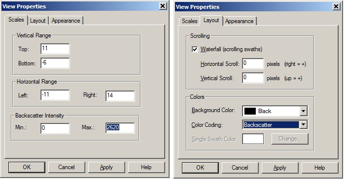
Set Color-coding to Backscatter (i.e. laser data raw intensity) and set the color-coding range to values between 0 and 3- to 4 thousand.
Additional Information
The ILRIS-HD has the following features and limitations:
-
The maximum scanning range is 1800 meters, but the accuracy may depend on your exact scanner type
-
The maximum scan area covers 40° (effectively from -18 to +18)
-
The maximum expected number of beams (pixels) per second is 10000 (theoretically).
-
The actual number of beams depends on the on-line used settings, like scan interval, range and /or intensity blocking, etc. See Online Setup for more information.
-
The decoded raw intensity is a value between 0 and 255,000. However, the majority of the values will be less than 3 á 4 thousand, so you may use this scale for color-coding. The intensity depends on the target's surface being hit.
The scaled (normalized) intensity value is always between 0 and 255, and is derived from the raw intensity using some sort of a method.
Use registry key HKEY_CURRENT_USER\Software\QPS\Qinsy\8.0\Drivers\DrvLaser\ILRIS\<System Name>\Settings\NormalizeMethod to change the method for calculating the scaled intensity (method 1 is linear, 2 to 4 are non-linear, 2 is recommended).
Notice that a QPD always contains the scaled intensity, so for color-coding (quality) you should use this range of 0 to 255.
Improve Performance
Due to the enormous amount of data to be expected while scanning and recording, it is recommended to keep the system overhead as low as possible.
Here you'll find some tips and tricks in order to fine-tune your setup.
However, these are not strict rules, because each project is different and depends on the current situation and hardware being used. Your goal should be to keep your system CPU usage as low as possible.
HARDWARE
Storage
Make use of Solid State Drive (SSD), or fast SATA hard drive (7200 - 10000 rpm).
Network
Your network card speed should never be lower than the scanner's network speed. Use a network card that can be configured for 100Mbit or 1Gbit speed. Do not use USB Networking Adapters, because this may result in loss of data when huge amounts of data are being broadcast.
Virus Scanner
Disable Virus Scanner or at least the setting 'Scan Files when Writing/Reading to/from disk'.
Task Manager CPU
General Task Manager CPU Usage should be less than 50%. CPU load of each display must be less than 10-15%.
Make sure that the 'Working Set (Memory)' column for process Multibeamer.exe and/or DrvResultOut.exe is not constantly increasing, especially during recording. For detailed information about this see the section Real-time Performance Monitoring below.
PROJECT PREPARATION
Controller Laser Device Settings
During project preparation, establish the optimum settings in order to achieve the required results.
The most benefit you will gain from setting the Min/Max Range limits, Scan Speed, Scan Rate, Scan Resolution, Angle Resolution, Vertical Area Selection, Scan Area Selection and Sector Reduction as well as possible.
Especially the Vertical or Scan Area Selection is very important. Make use of Mask schemes to define areas which you don't want to scan.
ONLINE
Raw Multibeam Display
Open only one Raw Multibeam Display and more important: do not use the options 'Show Big Dots' or 'Draw Lines'.
Navigation Display
Open only one Navigation Display.
Preferably disable DXF and TIFF layers or other big background files. Note that these layers should only be used during project preparation.
When 'object tracking' is enabled, do not zoom in too close. Keep in mind that the display should not be 'refreshed' more than 1x per second.
3D Point Cloud Display
It is not recommended to use a 3D Point Cloud Display, unless your hardware contains a high-spec video card.
Under Sensor settings set the Time window setting to a short period, e.g. 10 sec
Static Grid / Dynamic Grid
Storage to a grid is not recommended and should be purely for display purposes: e.g. for checking the scan coverage or for showing the 95% Confidence Level statistics.
If you do want to see the scan coverage then it is advisable to store to a sounding grid and not to the dynamic surface
Do not use a small cell-size; preferably not less than 1.0 meter.
If you notice in the Navigation Display that the real-time sounding grid is updated with a delay then please increase the cell-size or disable the storage completely.
Note that in Replay (offline) there are no limitations and you may use small cell-sizes, e.g. 0.10 meter.
OFFLINE
Replay
In Replay there are no limitations as mentioned above: use as many displays as you like, store to sounding grids with small cell-sizes, update the dynamic surface, etc.
All this may only affect the replay speed, but the data integrity of your final DTM processing files should be fine.
COMPUTATION SETUP
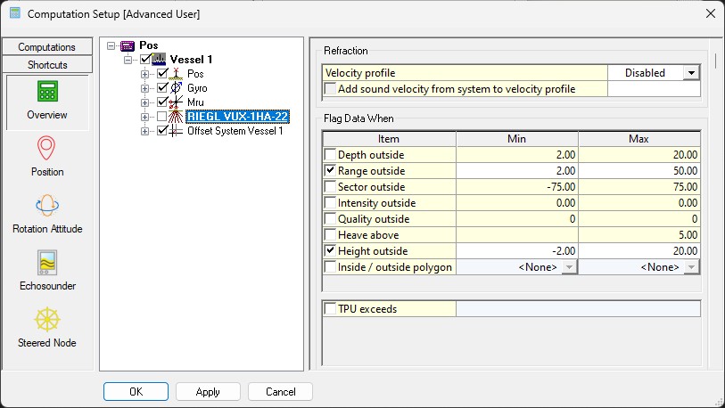
While working online, disabling the laser system in your Computation Setup will have the most effect on the performance
The final footprints will not be geo-referenced, nor corrected for motion, heading or timing in real-time, which will save a tremendous amount of CPU power and memory usage.
This tip allows you to get the most out of your scanner: maximum scanning speed and maximum scanning rate, without the risk of losing scans due to performance issues.
Drawback is that no DTM file (e.g. QPD) is created, nor a grid is filled, while working online.
In order to create a final DTM and/or Grid file you just need to Replay the recorded databases afterwards or load the recorded databases straight into Qimera for further processing.
If you experience problems using your laser scanner in combination with this driver or if you need additional information or support then please attach the daily laser log-file when submitting your JIRA support ticket.
At the bottom of this section you'll find the information on where to find this daily laser log file
Network Problems
Windows Firewall
A commonly reported problem is that network data is blocked by the Windows Firewall.
When this happens you may see that data does come in using other utilities (like the I/O Tester or the manufacturer's own software), but that the Qinsy driver does not accept any data.
The following (Windows 10) steps may solve this:
-
Go offline, open the PC Settings (Start menu, Settings)
-
Select Windows Firewall (Privacy & security, Windows Security, Firewall & network protection)
-
Select Advanced settings
-
Select Inbound Rules, highlight all 'Driver for Laser Scanning' entries and delete them using the right mouse popup menu (or Del key)
-
If you now go online, the Windows Security Alert message will pop up: now it is important to Allow access!
Multiple Network Cards
Another possible problem could be that your computer has more than one network card installed (e.g. LAN and WIFI) but within the same sub-net mask range (255.255.255.0).
It is recommended to make the first three digits unique for each network card IP address.
You may check the daily laser log-file; it will show the IP addresses for all available network adapters and indicates which one the driver will try to use automatically:
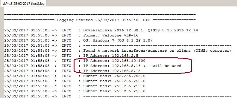
Please check that the driver is using the correct one!
Missing Data
If you occasionally experience gaps in your data, this may be caused by a general Windows setting that affects the data throughput of your network card.
Change the following registry key: HKEY_LOCAL_MACHINE\SOFTWARE\Microsoft\Windows NT\CurrentVersion\Multimedia\SystemProfile\NetworkThrottlingIndex
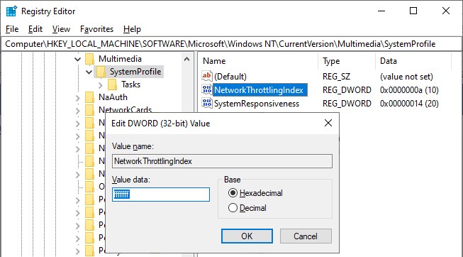
Set the new value to ffffffff (which will tell Windows to disable network throttling) and restart the computer.
Note that disabling network throttling may affect playing multimedia on your computer, but for laser scanning operations it is advisable to have a maximum data throughput of your network.
Daily Laser Log File
All user actions, system information and reported errors are logged in a daily laser log file which can be found in the current project's LogFiles subfolder.
The filename convention for this ASCII log-file is <System Name> DD-MM-YYYY.log, so every day there will be a new one.
Note that all time stamps in this log file are by default in UTC. An advanced user may change this to local time zone (LTZ) by changing the registry key:
HKEY_CURRENT_USER\Software\QPS\QINSy\8.0\Drivers\DrvLaser\Settings\TimeLogFileUtc value from 1 to 0.