Description
Driver for network data from a Kongsberg Mesotech MS1000 PC Based Sonar.
The driver connects as a client via TCP/IP to the MS1000 Sonar Software running on either the same or on a different computer than Qinsy.
The driver can decode the raw pixel data as a single channel sidescan system and the digitized points as a multibeam system.
The driver will always assume that the MS1000 sonar is correctly time synchronized with UTC, it will decode the Timestamp from the sonar message and assume it is correct and in UTC.
The driver can not communicate with the scanner head directly nor control it, therefore the MS1000 software program is required.
Note that the driver was tested with the MS1000 software version 4.32Beta9, older versions are not guaranteed to work. Please contact Mesotech for the latest software.
Driver Information
|
Driver |
Kongsberg Mesotech MS1000 |
Interface Type |
TCP-IP |
Driver Class Type |
Counted |
|---|---|---|---|---|---|
|
Yes |
Input / Output |
Input |
Executable |
DrvQpsCounted.exe |
|
|
Related Systems |
|
||||
|
Related Pages |
|
||||
Decoding Notes
|
1. |
Multibeam |
The driver decodes the orientation of the head as the beam angle and the range in one way travel time in seconds. It will also group the received beams into a single ping container by looking at the direction of rotation. As soon as the rotation direction inverts then the collected beams are grouped as a single ping and sent to the rest of Qinsy. The arrival of the beam after the direction change is considered to be the first beam of the next ping. The time offsets of the beams with respect to the first beam are calculated and stored within the beam data. The Beam Angles from the scanner are converted to Qinsy convention hard coded in the driver. The device Id from the string is used as slot number, the string will only be used if the Id from the string matches the Slot ID as entered in Database Setup. Important Driver will only decode properly when the direction of the scanner is flipping.
If the scanner head is constantly turning in one direction then the data will not be decoded.
|
|---|---|---|
|
2. |
Sidescan |
The MS1000 Message contains up to 5000 8 bits imagery samples. This is converted in the driver to Qinsy 16 bits format by multiplying with 256. |
|
3. |
Gyro |
The MS1000 sonar scanner head can contain an optional magnetic compass which can be decoded by the driver, see chapter below on how to set this up. |
|
4. |
Rotation Angles |
The MS1000 Angle of the Scanner head can be decoded by Qinsy as a "Rotation Angle Sensor" observation. With this the possibility Qinsy opens up to visualize a Sector Scan Image into the sounding grid, see below for setup. For dual axis transducer heads the second rotation angle (pan) can also be decoded. Note that this will be supported in future MS1000 versions of software. |
Info
The driver will decode and use the time stamp that is contained in the message. The time is considered to be valid for the moment of sending and is in the UTC time frame.
The message also contains a Channel Id which is used for the decoding. The MS1000 Software supports multiple sonar heads so the channel Id is used as slot number in Qinsy to identify the originating sonar head.
Data Message contains a "valid" flag. If this flag is 0 then the message is considered to be invalid and will not be decoded.
The Data message will only be decoded if several integrity checks on various data fields were passed.
System Configuration
The MS1000 software auto connects to clients requesting for data so in principle no additional settings are required in the program.
MS1000 scanner modes
The MS1000 can be used in three modes together with Qinsy:
|
1. |
Sidescan |
The scanner transducer head will not rotate but will be in a fixed angle facing port or starboard, Qinsy will show a traditional sidescan waterfall. |
|---|---|---|
|
2. |
Profiling |
The scanner is mounted horizontally and will be scanning a sector. Bottom is detected by MS1000 software and decoded by Qinsy as a multibeam system. |
|
3. |
Sector Scan |
The MS1000 scanner head is mounted vertically and will be scanning a sector or circularly. The Acoustic data is decoded as a regular sidescan system but the scan angle is also decoded by Qinsy. By means of the so-called object linking functionality and the decoded scan angle, it is possible to fill a sounding grid with sidescan data in a circular fashion similar to an image shown by sector scanning sonar. |
Mounting the scanner
The sonar scanner should be mounted in such a way that the decode angle is 180 for a vertically mounted scanner (transducer down) with transducer face pointing aft, or for a horizontally mounted scanner transducer pointing forward, face down.
The driver has only been tested with these two configurations.
Database Setup
Start the Database Setup program to modify the system setup.
Object linking for Sector scan visualization
Add a second object to the Database, also add one node on this object that can serve as the link node. Add a new link from the vessel object - Scanner Node to the pivot node on the second object.
Make sure to define the sidescan system channel on the new object, orientation of the sidescan channel should be set to Forward.
Also define the rotation sensor on the second object. This should be sufficient, Online the filling of the grid by the sidescan should be setup appropriately. Minimal grid layer type can be used to guarantee overwriting of previous scan data.
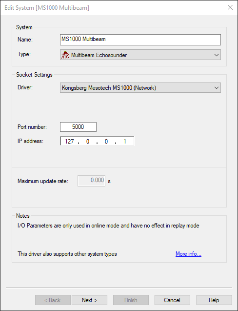
Multibeam
Main Head
|
Name |
For example: "MS1000 Multibeam" |
|---|---|
|
Type |
Multibeam Echosounder |
|
Driver |
Kongsberg Mesotech MS1000(Network) |
|
Port number |
5000 |
|
IP Address |
127.0.0.1 (MS1000 software run on own pc xxx.xxx.xxx.xxx (IP address of pc running the MS1000 software) |
Secondary Head
For a dual head system add another "Multibeam Echosounder" system, select same IP number and port number and a different slot number corresponding with the Sonar Head Number (#).
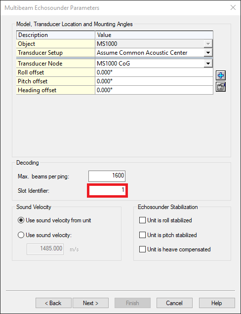
Multibeam Echosounder Parameters
|
Max Beam Count |
1600 |
|---|---|
|
Slot Identifier |
Sonar Head Number (#) as visible in the MS1000 software. |
|
Rotation offset |
For multibeam systems keep in mind that we consider a horizontal mounted, transducer face down to be the reference. Any deviation from that should be accounted for in the Rotation offsets. |
Echosounder Accuracy Parameters & Echosounder Correction
Can be left at default settings if unknown.
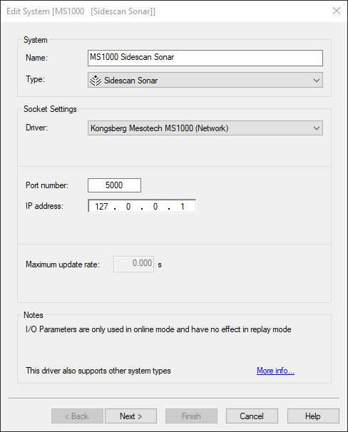
Sidescan
|
Name |
For example: "MS1000 Sidescan Sonar" |
|---|---|
|
Type |
Sidescan Sonar |
|
Driver |
Kongsberg Mesotech MS1000(Network) |
|
Port number |
5000 |
|
IP Address |
127.0.0.1 (MS1000 software run on own pc) xxx.xxx.xxx.xxx (IP address of pc running the MS1000 software) |
Sidescan Sonar Channel Setup
Add a new channel:
|
Transducer |
Select the correct node (location) |
|---|---|
|
Orientation |
Forward (when positioned vertically, transducer face pointing aft) |
|
Slot ID |
Sonar Head Number (#) as visible in the MS1000 software. |
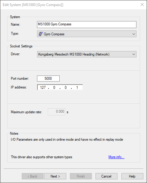
Gyro
|
Name |
For example: "MS1000 Sidescan Sonar" |
|---|---|
|
Type |
Gyro Compass |
|
Driver |
Kongsberg Mesotech MS1000 Heading (Network) |
|
Port number |
5000 |
|
IP Address |
127.0.0.1 (MS1000 software run on own pc) xxx.xxx.xxx.xxx (IP address of pc running the MS1000 software) |
Internal Gyro
The ‘Sonar Heading' is valid only when there’s a built-in compass available, otherwise it will be an invalid number: 3276800.
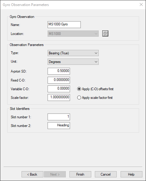
Gyro Observation Parameters
|
Name |
Observation name, for example 'MS1000 Gyro' |
|---|---|
|
Location |
Correct object |
|
Slot ID 1 |
Sonar Head Number (#) as visible in the MS1000 software. |
|
Slot ID 2 |
Should be set to Heading (this is case sensitive) |
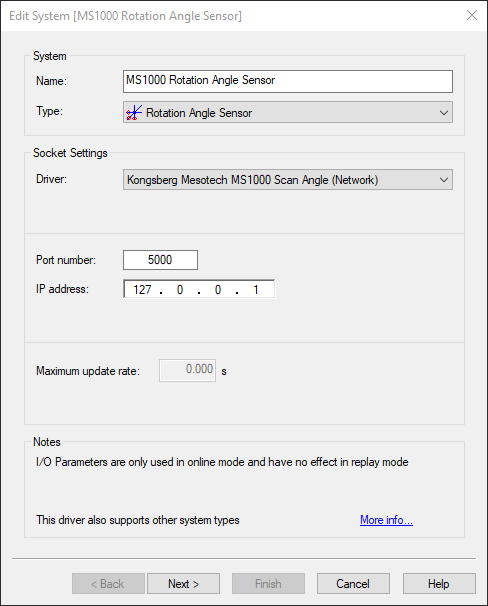
Rotation Angle Sensor
Rotation information
The Rotation angles are only going to be useful if the system is going to be used when the MS1000 is interfaced as Sidescan Sonar.
|
Name |
For example: "MS1000 Sidescan Sonar" |
|---|---|
|
Type |
Gyro Compass |
|
Driver |
Kongsberg Mesotech MS1000 Scan Angle(Network) |
|
Port number |
5000 |
|
IP Address |
127.0.0.1 (MS1000 software run on own pc) xxx.xxx.xxx.xxx (IP address of pc running the MS1000 software) |
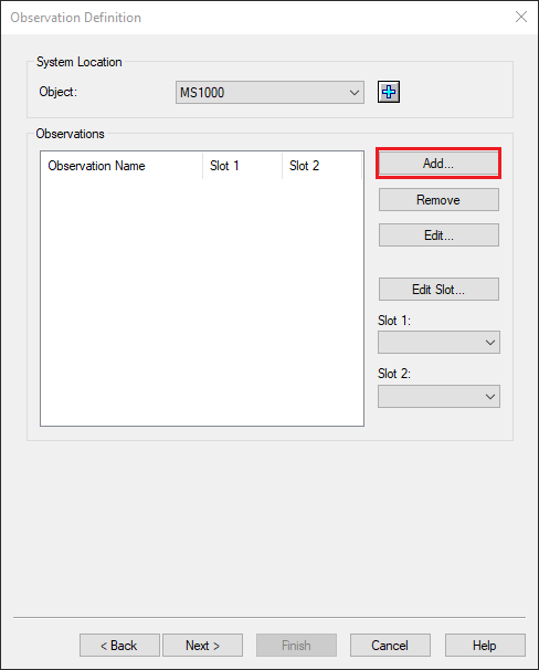
Observation Definition
|

|
|
|
|
Click on add |
Select Type: 'Rotation (Z)' Name: example 'Rotation (Z)' At Node: any node on the object |
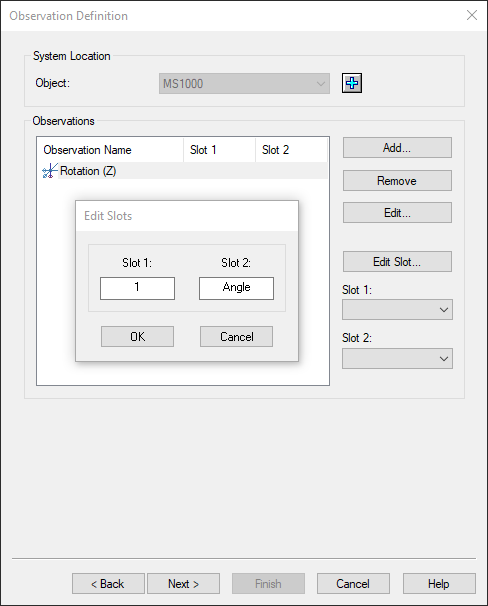
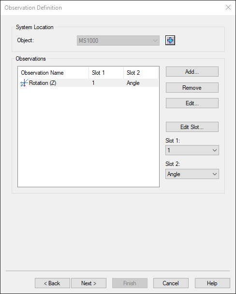
Slot 1: Sonar Head Number (#) as visible in the MS1000 software. Slot 2: Should be set to 'Angle' (case sensitive).
|
Click Next & Finish |
Recap:
|
Type |
Rotation (Z) |
|---|---|
|
Name |
For example 'Rotation (Z)' |
|
At Node |
Any node on the object |
|
Slot 1 |
Sonar Head Number (#) as visible in the MS1000 software. |
|
Slot 2 |
Should be set to 'Angle' (case sensitive). |
Rotation Angle
For dual axis scanners the second angle can also be decoded, in that case Slot 2 should be set to "Pan" (case sensitive).
Computation Setup
If you are going to perform a sector scan, make sure that you have a second Computation in which the MS1000 is activated.
Additionally make sure that the Heading Priority is set to the Rotation(Z) observation:
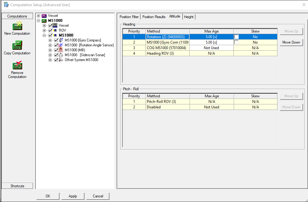
Rotation information
Keep in mind that the Rotation angle sensor should not be active if the MS1000 is used as multibeam system.
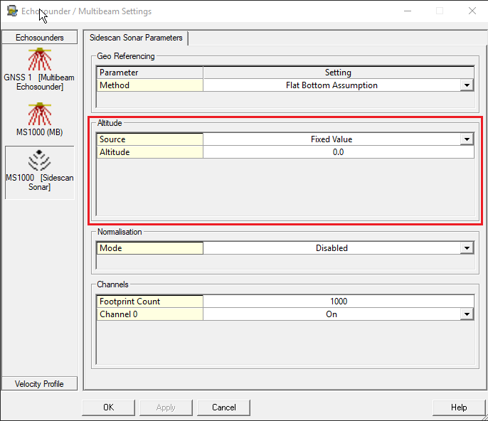
Echosounder Settings
In case of Sector Scan mode, make sure to change the attitude in the Sidescan Sonar Paramaters to Fixed value, otherwise the Sidescan sonar will try to track the bottom, however this is difficult in case of a Sector scan.