
Description
The Klein Marine Systems socket driver can be used to interface a Klein 3000/3900/5000/5000 Version 2/HydroChart 3500/4000/4900/Ma-x View 600 sidescan sonar system into Qinsy.
This driver can be used to read the following data into Qinsy:
-
Side Scan Sonar
-
Multibeam (Bathymetry - 5000/5000 Version 2 only)
-
Auxiliary data
-
Heading - Gyro Compass
-
Pitch, Roll - Pitch Roll and Heave Sensor
-
Altitude - Underwater Sensor
-
Depth - Underwater Sensor
-
-
Angle look Sonar (Ma-x view 600 only)
ALS – Stands for Angle Look Sonar. This is a technique that uses sonar technology to look below and slightly ahead of the vehicle to provide an overlapping image of the sea floor. -
Online User interface to control the operational parameters of the Klein sonar.
The Klein 5000 series are capable of delivering multiple scan lines per ping.
The Klein 5000 Version 2 is the successor of the 5000 but for this system the beam forming calculation is done within the driver, not in the TPU (Klein topside) anymore.
For 5000/5000 V2/HydroChart 3500 systems that are equipped with additional bathymetric channels the interferometric bathymetric angles can be calculated.
This is done internally by the driver with the help of the Klein dll's.
Note that this is an expansive operation which will cause quite some cpu load (about 10% load on a modern computer).
The beam angles are calculated with the sound velocity that is reported by the Klein sonar.
If it uses an internal sound velocity sensor then those values are used, otherwise the user defined value as entered in the User Interface of the driver is used.
Driver Information
Coding Notes
Decoding Notes
Timing
If a proper Time Synchronization system is used by Qinsy then the ping time from the Klein data is decoded and used.
Note that only minutes and seconds are decoded and mixed with the current Qinsy time to prevent any offset due to the wrong time zones as we have encountered in the field.
Multibeam Data
The decoded beam angles refer to the transducer face normal. The angles are calculated with the current sound velocity, this will be the manual sound velocity as set up in the user interface or the sound velocity from a sensor if the fish contains one.
Each sample that has a valid angle will be reported as a multibeam footprint. The number of beams per ping will vary but will typically be around 2500 beams per ping per side for a 100 meter range. Samples that have an invalid beam angle will be discarded for bathymetric purposes.
The number of roll values decoded per ping is currently limited to one roll value per ping. This may give small errors in the final footprint calculation. It is advisable to use an external motion sensor for this, for example a POS M/V.
Multibeam data:
-
Each beam contains a quality flag between 0-100, this is the quality percentage. This can be used to block data on. Quality 0 is very low, Quality 100 is best. The quality can be used for data cleaning on Quality.
A default quality acceptance range can be 65-100, anything below this is flagged as bad quality. -
If intensity data is available it is filled, otherwise it remains zero.
System Interfacing
Interfacing Notes
The Klein topside unit (TPU) should be connected to the Qinsy PC through the network Ethernet port. The network settings on both TPU and Qinsy PC should be valid.
The TPU is set at the factory to IP address 192.168.0.81. Make sure that both IP addresses are within the same sub-net.
Connect the TPU to the Qinsy PC via a direct cross over network cable or through a hub or switch.
Qinsy Config
Database Setup
Start the Database Setup program of Qinsy in order to define various new systems.
Sidescan Sonar
Add a new system, select type "Sidescan Sonar" and the required driver (f.i. "Klein Marine Systems 3000" for a 3000 system, or "Klein Marine Systems HydroChart 3500" for a HC3500 system).
The IP Address of the TPU should be entered here. The port number may be set to zero, it is not used.
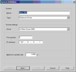
Press 'Next' button.
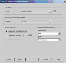
Select "Use sound velocity from unit".
The Manufacturer and Model are for administrative purposes only, the settings will not influence the online operation.
Press 'Next' button
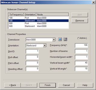
On this page we will define the channel setup of the system.
Klein 3000
Number of beams should be set to 1 for all channels.
The Klein 3000 is by default equipped with a dual frequency option, resulting in 4 channels.
The 3000 outputs data of the four channels in a specific order.
To decode this correctly you should define the following channels and assign the listed slot ID's:
|
Channel |
Low Frequency |
High Frequency |
||
|---|---|---|---|---|
|
Orientation |
Port |
Starboard |
Port |
Starboard |
|
Slot ID |
0 |
1 |
2 |
3 |
Klein 3900
The Klein 3900 can only operate on a single frequency: either low or high.
For this system just select two channels: the first port, the second starboard. Slot ID's can be left at zero.
Number of beams should be set to 1 for both channels.
Klein 5000/ 5000 V2
This system requires the definition of just two channels: the first port, the second starboard. Slot ID's can be left at zero.
Number of beams for both channels should be set to 4 for a 5400, 5 for a 5500, 8 for a 5800 system.
Press 'Finish' to finalize the creation of the new sidescan system.
Klein HydroChart 3500
Number of beams should be set to 1 for all channels.
The Klein Hydrochart is a single frequency device that uses one channel for port and one for starboard.
In order to decode the data correctly, you should define the following channels and assign the listed slot ID's:
|
Orientation |
Port |
Starboard |
||
|---|---|---|---|---|
|
Slot ID |
2 |
3 |
||
Klein 4000/4900
Number of beams should be set to 1 for all channels.
This is a single frequency device that uses one channel for port and one for starboard.
In order to decode the data correctly, you should define the following channels and assign the listed slot ID's:
|
Channel |
|
|
|---|---|---|
|
Orientation |
Port |
Starboard |
|
Slot ID |
2 |
3 |
Klein Ma-x View 600
Number of beams should be set to 1 for all channels.
To decode this correctly you should define the following channels and assign the listed slot ID's:
|
Channel |
Gap filled |
Side scan |
ALS |
|||
|---|---|---|---|---|---|---|
|
Orientation |
Port |
Starboard |
Port |
Starboard |
Port |
Starboard |
|
Slot ID |
0 |
1 |
2 |
3 |
4 |
5 |
Note
Klein Ma-x View 600 combines the sidescan with the ALS data to show a complete image. You can enable each channel as seen in the table above.
If you want to see more than 1 channel, then each channel (Gap filled, Side scan, ALS) needs to have its own frequency set.
Qinsy will group channels with the same frequency and having all 3 channels set with the same frequency could cause undefined behavior.
e.g. Gap filled 100 Hz, sidescan 90Hz, ALS 80Hz.
A low or high frequency setting does not impact the data processing or displays.
Multibeam Data (5000/5000 V2/HydroChart 3500 only)
If the sidescan fish is equipped with additional transducers for bathymetric purposes then two multibeam systems should be defined in the setup to take advantage of this data.
Add a new multibeam system with the driver "Klein Marine Systems <type> Port". Choose same IP and port number as for the sidescan system. Set Maximum Beam count to 32768. C
hoose a node offset location, this should be the center of the transducer. The roll offset is typically +70 degrees for the port side when transducers are installed with a depression angle of 20 degrees.
Formula: Port Roll offset Qinsy = 90 - Depression Angle.
Add a second multibeam system for the starboard side, choose driver "Klein Marine Systems <type> Starboard". Again choose same IP and port as the Sidescan sonar system.
Choose a node offset location, this should be the center of the transducer. The roll offset is typically -70 degrees for the starboard side when transducers are installed with a depression angle of 20 degrees.
Formula: Starboard Roll offset Qinsy = -1 * (90 - Depression Angle).
Auxiliary Data Setup
The sidescan fish may be equipped with additional auxiliary sensors, which may optionally be decoded by the driver:
-
Motion
-
Magnetic compass
-
Pressure gauge
-
etc.
Pitch Roll Heave Sensor
If the sidescan fish is equipped with an internal KMS motion sensor then the roll values from the internal motion sensor data can be used.
Pitch, heading and in case this motion sensor is absent are taken from the internal gyro. If the fish doesn't contain that either, the returned values will be zero.
Add a new "Pitch Roll Heave Sensor" system, set same port and IP number as for the other systems.
Select the Fish CoG as the node offset location. The sign convention is unknown at the time of writing.
Gyro Compass
For the decoding of the gyro add a new Gyro system to the template database, select driver "Klein Marine Systems xxx (Heading)" and choose the exact same IP and port settings as for the sidescan system.
Underwater Sensor
For the decoding of Altitude and Pressure of the fish add a new "Underwater sensor system" to the template database and select driver "Klein Marine Systems xxx (Pressure and Altitude)" and choose the exact same IP and port settings as for the sidescan system.
Next, add two observations of type "Pressure" and "ROV Altitude", set units to PSI and meters respectively.
The Pressure sensor will output a voltage of 0-5 volts over the full measuring span. Depending on the measuring pressure range a scale factor should be set.
See table below for some typical sensor settings:
|
Pressure Sensor Range (PSI) |
Observation Scale Factor |
|---|---|
|
0-300 |
60 |
|
0-1500 |
300 |
|
0-3000 |
600 |
When a different pressure sensor is used you will have to calculate the Scale Factor and optional C-O yourself; default scale factor is Max Measuring range divided by the max voltage.
"ROV Depth" observation is also supported for a legacy of reasons but it is better to select the pressure and let Qinsy convert the pressure to ROV Depth.
For the decoding of the pitch and roll of the fish add an new Pitch, Roll and Heave system and select driver "Klein Marine Systems xxx R-P" and choose the exact same IP and port settings as for the sidescan system.
Note
In order to make this work correctly always select for all Klein sonar related systems the same model number, port number and IP number.
When you go online you should check that only one driver executable is started.
If two drivers are started, then for one system the model, port or IP is different.
Qinsy Online
Online
The Controller starts the driver when going online.
The driver retrieves its last saved windows state from the registry on startup.
On startup the driver will try to connect to the TPU automatically.
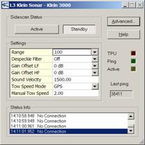
The driver window looks as follows:
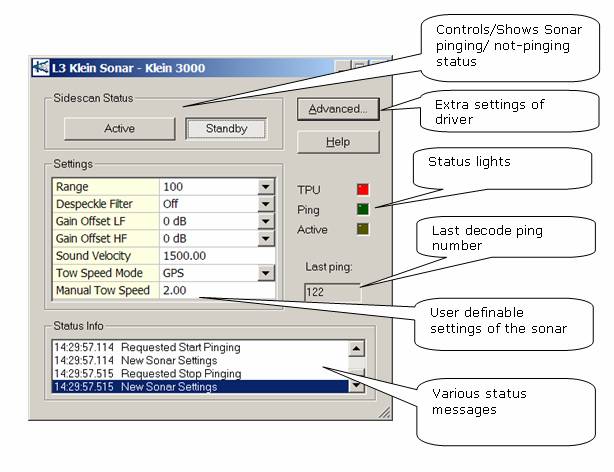
Sidescan status
The Active/Standby buttons reflect the current status of the Sonar system.
The user can activate pinging by pressing the Active button; the Standby button will command the sonar state in an idle state.
The Advanced button will show the advanced settings dialog (see below).
Status Lights
These status lights give the user insight into the status of the driver to TPU connection.
|
Led |
Behavior |
Explanation |
|---|---|---|
|
TPU |
Red |
If bright red then a master connection is established to the TPU. |
|
Blue |
If bright blue then a slave connection is established to the TPU. |
|
|
Off |
If not lit at all then the driver cannot make a connection. In the latter case check IP settings and whether TPU is powered on. |
|
|
Ping |
Blink |
This led lights up whenever a valid Sonar packet is decoded. |
|
Active |
Blink |
This led lights up when the sonar is in the active mode (=pinging). |
Settings
This table shows the current settings of the sonar system (if connected).
Most user definable settings are supported but the following parameters are not supported (yet): layback parameters, responder divisor and responder frequency, Sub-bottom profiling options.
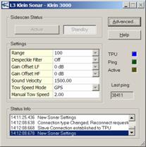
When driver is connected to the TPU through a Slave connection then the user cannot change the settings; the controls are read-only. Note that settings can only be changed in Master connection mode.
If user changes a setting then a message is sent to the TPU with the new configuration. Normally the new setting will be accepted by the TPU but if a setting is denied for some reason then the previous setting is visible again.
For more details on the settings please refer to the sonar manuals.
Note
3000/3900 only: The pulse length of the transmission pulse is not user definable; instead the driver will adjust the pulse length depending on the selected range.
Refer to section below about the used pulse length vs. range table.
Note
Hydrochart 3500 only: The pulse length of the transmission pulse is not user definable; the HydroChart 3500 will always use a chirp of 4 ms.
Note
The HydroChart 3500 supports setting a sonar saturation detection threshold as a percentage of the receiver scale.
Each data sample is flagged if that data value was obtained with the receiver exceeds the specified saturation threshold.
The setting of this option is supported by the driver, but Qinsy ignores the saturation flag in the data.
Status Info
This list shows the history of the system/connection status. Every time a major event takes place it is reported here together with the local time.
Last Ping
The last decoded ping number is shown here.
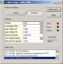
Connection Mode (Master/Slave)
If connection is established successfully then the TPU light will be bright red or blue and the Status Info window will show a message "XXXXX Connection established to TPU".
XXXXX can be Master or Slave. Check network settings and power on TPU if connection fails. The driver will try to (re-) connect to the TPU every second when no connection could be established.
Master/Slave concept: The TPU can connect to multiple programs or drivers but only one connection can be the Master.
The Master connection allows change of operational settings in the TPU and reception of sonar whereas Slave connections only allow the reception of sonar data.
Typically the driver is used as a Master connection and changes of operational parameters are done from the driver, but it is also possible to make the Klein SonarPro software the Master.
The driver is then operated in Slave mode only to receive the sonar data.
|
|
|
|
driver could not connect at all |
master connection established |
slave connection established |
Advanced Settings
Pressing the 'Advanced ...' button will launch the Advanced Settings dialog.
See below for a screen capture of the dialog:
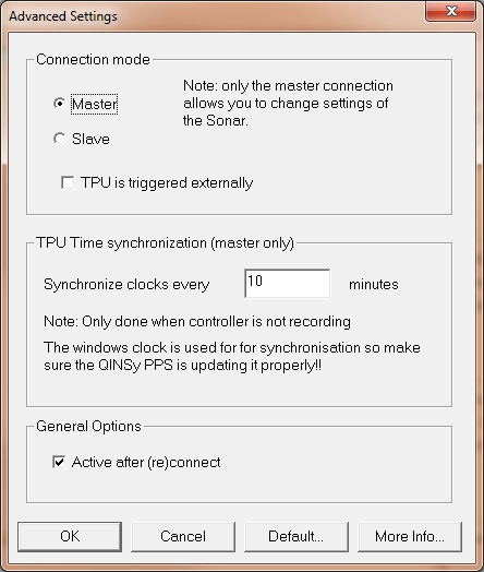
Connection mode
Select if connection should be a slave or a master connection; default is master.
If you are using Klein's own SonarPro software to control the sonar then you can connect as slave.
TPU time synchronization
The driver will set the clock inside the TPU identical to the Qinsy PC every time the logging is stopped in the Controller AND the user definable interval has expired; default is 15 minutes.
Note that this uses the local MSWindows clock so make sure the Time Synchronization is synchronizing the MSWindows clock properly.
This is a setting in the Database Setup of the Time Synchronisation System.
General Options
Active after (re)connect
If this option is enabled then the sidescan sonar system will be commanded to start pinging as soon as the connection is established.
This only applies to a Master connection.
The settings are all stored in registry and retrieved upon startup of the driver.
Clock Synchronization
Timing is very important. The driver decodes the observation time from the sonar data packets. It is therefore of utmost importance that the clocks of Qinsy and the TPU are synchronized.
If Qinsy is the master then the clock in the TPU is automatically synchronized with the Qinsy clock by the driver every time a connection is established (typically only at startup) and every user defined interval when recording is stopped.
Every time the clock is synchronized the Status info will show "TPU clock synchronized". The user defined clock sync interval can be selected in the Advanced settings.
If Qinsy driver operates in slave mode then the driver cannot synchronize the clock, this requires a master connection.
If the SonarPro software operates as Master then it should either run on the same PC as Qinsy or the computer on which SonarPro runs must be time synchronized to the Qinsy PC.
You can use a freeware NTP Server/client for this (accuracies may vary).
QPS strongly advises to use the driver in MASTER CONNECTION MODE to prevent timing issues.
Note on MSWindows clock
For correct clock synchronization of the TPU it is essential that Qinsy is using a Time Synchronization System AND that the MSWindows clock is properly synchronized to UTC.
The MSWindows clock can only be set by Qinsy Time Synchronization when the MSWindows UAC (User Account Control) setting is disabled.
Viewing Additional settings
Press the "More Info..." button to show a dialog with some of the the current bathymetric processing settings.
This is only used for the 5000 or 5000 V2 system.
This may be interesting if you do not know the current depression angles (mounting angles) of the transducers.
Klein 5000 and 5000 V2
Signal processing tasks that were formerly executed in the TPU are now executed by the Qinsy driver. This will cause some CPU load.
The average CPU load for the Klein sonar driver will be around 10% on a modern quad core machine (2013).
The Signal processing/Beam forming DLL requires two sub folders in the Qinsy program folder called
BathyParms
-
Contains some bathy settings which are stored together with the essential "towfish.cal" file.
This file contains the system dependent settings on depression angles and stave distances and is essential for the correct calculation of the bathymetry data.
MFReplica
-
Contains files that describe the possible tx pulse wave forms.
These folders will be created automatically by the driver when started in "5000 Version 2" mode.
Without this folder the signals will not be processed.
Warning
For bathymetric processing the correct calibration file (unique for your Klein system) must be placed in the Qinsy program files subfolder "BathyParms".
This file must be renamed to "towfish.cal". If this folder does not yet exist then go online once, the driver will create the essential folders automatically on startup.
Then go offline, and rename the file.
If the calculated bathymetry looks very unrealistic, the calibration file will be the first to look at because a non-matching calibration file will be a cause for this.
Additional Info
Drivers IO Notes
Various driver options are supported:
|
3900 |
Start in Klein 3900 Mode. |
|
5000 |
Start in Klein 5000 Mode. |
|
5000v2 |
Start in Klein 5000 Version 2 mode. |
|
HC3500 |
Start in Klein HydroChart 3500 mode. |
|
4000 |
Start in Klein 4000 Mode. |
|
4900 |
Start in Klein 4900 Mode. |
|
MAX600 |
Start in Klein Ma-x view 600 Mode. |
If no model parameter is provided the driver will start in Klein 3000 Mode.