
Description
This is a driver with user-interface in order to encode messages for - and decode messages from an iXblue INS that supports the STD BIN protocol.
Info
Note that the input of this driver works with versions 1 - 5 of the iXblue standard binary protocol.
Note that the output of this driver only works with version 3 and higher of the iXblue standard binary protocol.
During normal operation the INS will establish an accurate position for the ROV based on the integration of Inertial, Doppler, USBL, Depth Sensor and Surface Positioning (Computation Node Result) information.
This driver can send the necessary surface positioning information to the INS in order to enhance the INS solution. At the same time it will read and decode the integrated accurate ROV position and attitude data, which can be used in a separate Computation.
There are 3 versions of this driver:
-
Serial
-
Network - TCP
-
Network - UDP
The user-interface for all drivers is exactly the same, only the I/O protocol is different.
See also the Interfacing Notes at the System Interfacing tab.
In case your setup does not require to receive any data from the unit, and you only need to send data to the INS, see the additional comment in the Output setup section at the Qinsy Config tab.
Driver Information
Click here to expand Driver Information
Decoding Notes
Encoding Notes
Interfacing Notes
System Config
This part explains how to set up the iXblue web interface.
Click to expand...
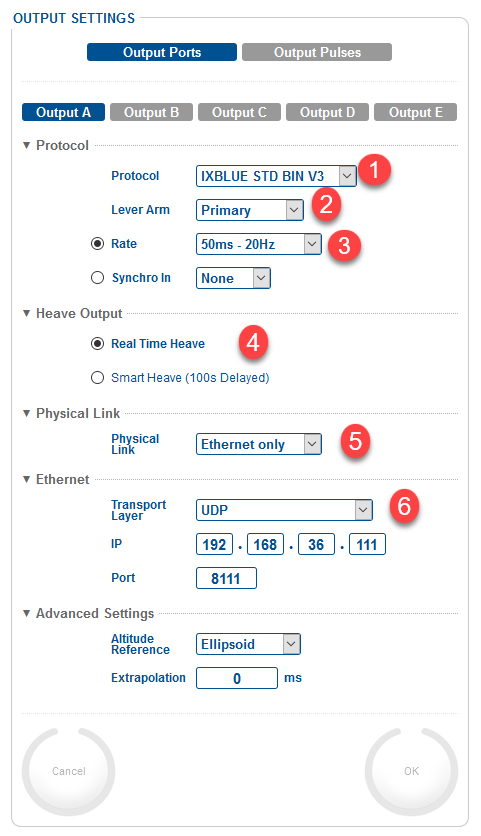
Output
-
Only work with Version 3 of the Std Bin format.
-
Make sure to set up the correct Lever Arm and that it corresponds with what is set up in Qinsy. (In one or the other, not both)
-
Recommended update Rate is 20-25 Hz with a max of 50 Hz.
-
You can still log Smart heave via a Miscellaneous system in Qinsy if Real Time Heave is selected here.
-
Either Serial or Network can be selected here.
-
The following network options work for Qinsy:
-
UDP (example above)
-
UDP Broadcast
-
TCP Server
-
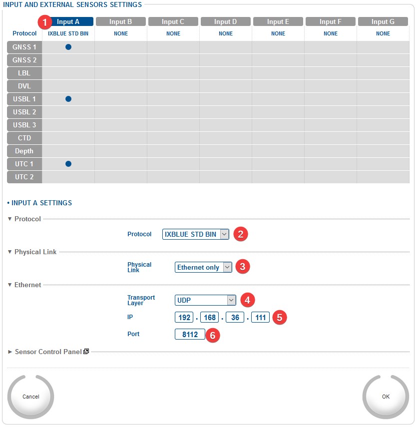
Input
Network settings
-
Select the input of which you want to change the settings
-
Select the iXblue Std Bin format
-
Both Ethernet and Serial can be used.
-
If Ethernet is selected then the following options can be used:
-
UDP (example above)
-
UDP Broadcast
-
TCP Server
-
-
Enter the IP address of the Qinsy PC
-
Qinsy sends the data back on port + 1.
In Output port 8111 was entered so in this case Qinsy will send back on 8112.
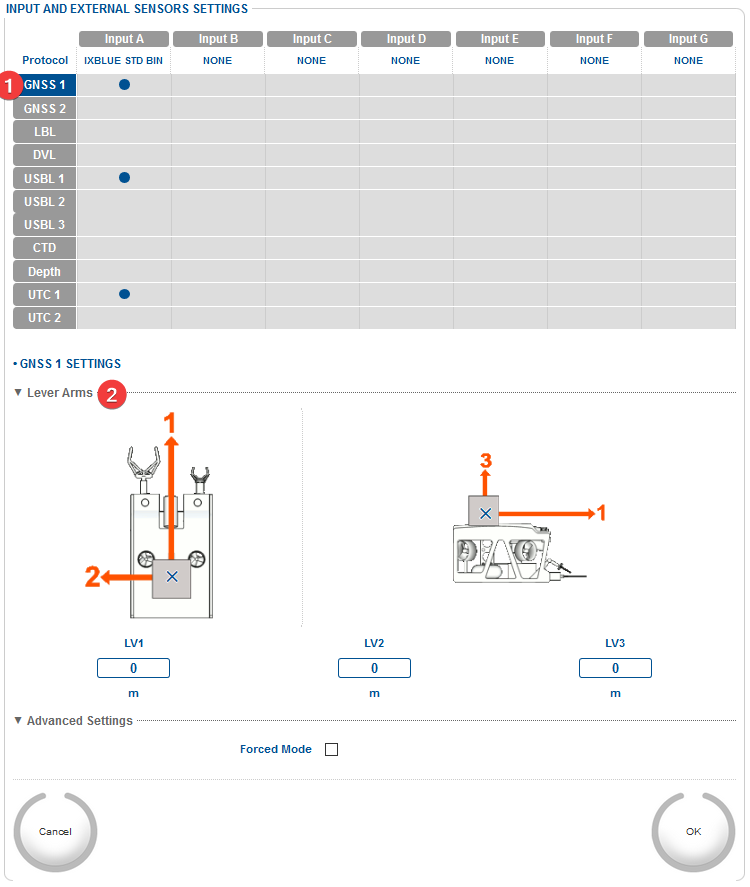
GNSS settings
-
In this example GPS1 is selected. Make sure the same is set for the USBL ID in the Qinsy User interface.
-
Make sure to set up the correct Lever Arm and that it corresponds with what is set up in Qinsy. (In one or the other, not both)
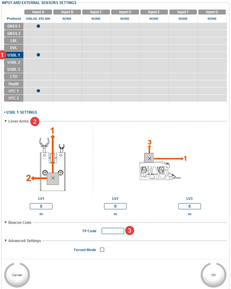
USBL Settings
-
In this example USBL 1 is selected. Make sure the same is set for the USBL ID in the Qinsy User interface.
-
Make sure this Lever Arm matches with what was set up in Qinsy.
-
No need to enter a TP Code.
UTC Settings
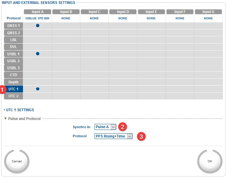
-
Select the UTC item
-
Select the correct pulse port
-
Make sure this is set up correctly, especially the order of Pulse and Time.
Qinsy Configuration
All systems can be set up as normal in Qinsy Database Setup, using the slot IDs described below, to determine which source of data to use.
More information can be found under the tab Coding Notes.
General driver info
|
Port number |
Should be the same as the output port on the iXblue web interface. |
|---|---|
|
IP address |
Default is 192.168.36.xxx
|
There are 3 options on how to work with this driver:
|
Input only |
No output selected in the online user interface |
|---|---|
|
Input & Output |
Serial
UDP
TCP
|
|
Output only |
Only add an output driver. Qinsy will output on the port that is selected in the template. |
Position Navigation system
Click to expand...
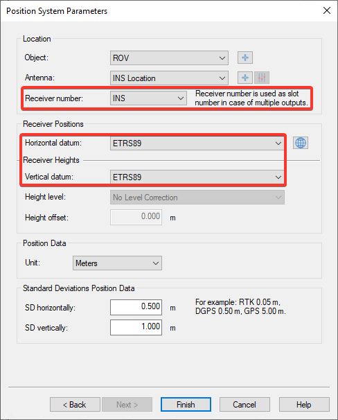
|
Receiver number
|
Slot ID |
What is it? |
|---|---|---|
|
INS |
Position result from the INS |
|
|
GPS1 |
Position input from GPS 1 as set up in the INS |
|
|
GPS2 |
Position input from GPS 2 as set up in the INS |
|
|
GPSMANUAL |
Manual position that was set in the INS |
|
|
USBL1 |
Position input from USBL 1 as set up in the INS |
|
|
USBL2 |
Position input from USBL 2 as set up in the INS |
|
|
USBL3 |
Position input from USBL 3 as set up in the INS |
|
|
LBL<X>_B<Y> |
Position input from LBLX (where X is 1,2,3, or 4) with beacon ID in the range "B00" through "B99" Info
|
|
|
Receiver Positions |
Select the datum the INS is outputting on. |
|
Gyro Compass
Click to expand...
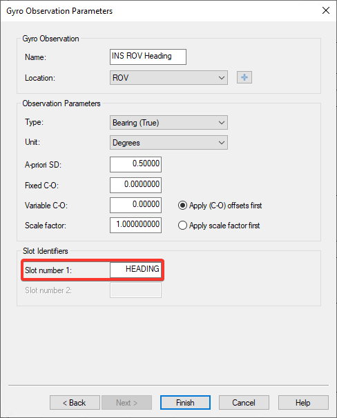
|
Slot ID |
Enter HEADING in order to decode the heading message. |
|---|
Pitch Roll Heave Sensor
Click to expand...
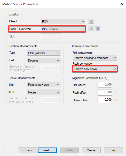
|
Node (Lever Arm): |
Make sure this offset matches with the Lever Arm selected in the iXblue web-interface. |
|
|
Conventions |
Item |
Convention |
|
Roll |
Positive heeling to starboard |
|
|
Pitch |
Positive bow down |
|
|
Heave |
Positive upwards |
|
Underwater Sensor
Click to expand...
-
After setting up the communication on the first page you can now Add the observations you want to decode:
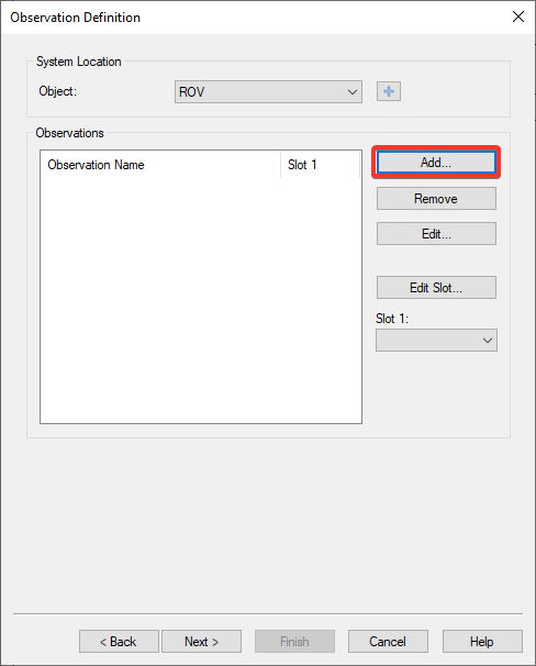
-
Select the correct Observation and Location.
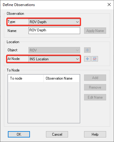
|
Observation Type |
You can select one of the following options:
|
|---|---|
|
Location - At Node |
Location of sensor in iXblue web interface. |
-
Make sure to select the correct Slot Value. See tab page Coding Notes for more information.
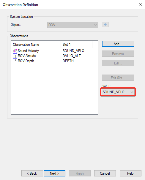
Note that there are two ROV Depth observations available: one with Slot "DEPTH" and the other one with Slot "INS_HEIGHT".
The first one will decode the raw depth reading as reported by the external depth sensor and the latter will use the decoded height from the INS position but with reversed sign. -
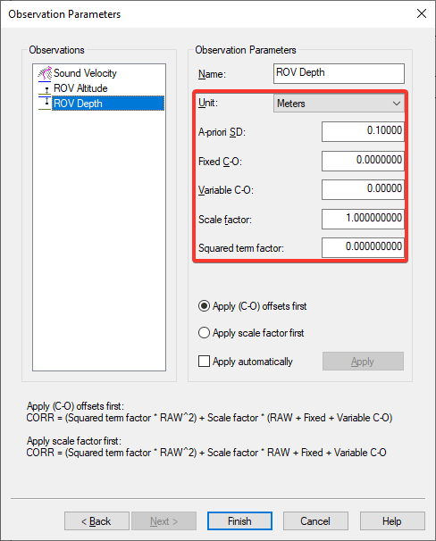
Select the correct Unit and enter corrections if required.
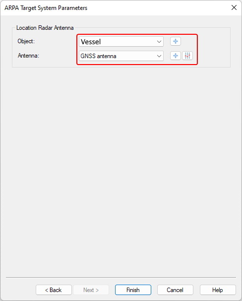
ARPA System
Click to expand...
The ARPA system can be used to expose LBL or USBL their positions. In order to set this up a selection of the vessel object and the object its radar antenna.
Output (Only)
Qinsy Online
The driver has user-interface, and therefore will always be present in the Windows task bar.
When going on-line for the first time, locate the driver, and change the Setup parameters:
Output datum
Note that the default Output datum is Survey Datum (Project datum).
Driver online user interface
Driver User Interface pages
Click to expand...
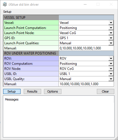
Driver Layout Menu: Setup
|
|
VESSEL SETUP |
|||
|---|---|---|---|---|
|
Vessel: |
Select from the available defined objects the vessel from which the ROV will be launched. |
|||
|
Launch Point Computation: |
Select the computation for the launch point of the ROV on the vessel. This output of this computation will be used for the GPS1 message. |
|||
|
Launch Point Node: |
Select the node for the launch point of the ROV on the vessel. This node will be output as the GPS1 message. |
|||
|
GNSS Identification: |
This setting should match with the setting on the input page of the iXblue interface. Options are:
If GNSS 1 is set in the iXblue web interface like shown in the picture: 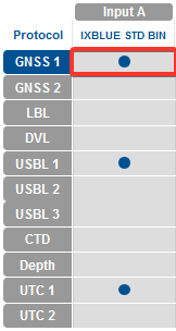
You should select GPS 1 as well in the Qinsy user interface. |
|||
|
Launch Point Quality: |
Select whether to use the qualities computed by the Computation (based on the SDs configured in Database Setup) or Manual qualities for the message. |
|||
|
Manual:
|
Manual quality values for the GPS1 message. Enter the following values comma-separated: quality, latitude SD, longitude SD, height SD, latitude/longitude covariance. |
|||
|
Quality
|
Also known as Solution mode.
|
|||
|
Quality indicator |
Corresponding SD attributed to GPS position fix if no GST is received |
Positioning system mode indicator |
||
|
0 |
Data invalid |
N/A |
||
|
1 |
10 m |
Natural |
||
|
2 |
3 m |
Differential |
||
|
3 |
10 m |
Military |
||
|
4 |
0.1 m |
RTK |
||
|
5 |
|
Float RTK |
||
|
6-25 |
Data invalid |
Other mode |
||
|
Latitude SD |
Standard deviation of the Latitude |
|||
|
Longitude SD |
Standard deviation of the Longitude |
|||
|
Height SD |
Standard deviation of the Height |
|||
|
Latitude/Longitude covariance |
Also known as HDOP |
|||
|
|
ROV USBL POSITIONING |
|||
|
ROV: |
Select the ROV object. |
|||
|
ROV Computation: |
Select the computation that is used to compute the position of the ROV under water. |
|||
|
ROV Node: |
Select the node for which the calculated position should be sent to the INS in the USBL1 message. |
|||
|
USBL Identification: |
This setting should match with the setting on the input page of the iXblue interface. Options are:
If USBL 1 is set in the iXblue web interface like shown in the picture: 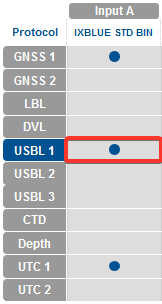
You should select USBL 1 as well in the Qinsy user interface. |
|||
|
Manual |
Manual quality values for the USBL1 message. Enter the following values comma-separated: latitude SD, longitude SD, height SD, latitude/longitude covariance. |
|||
|
Latitude SD |
Standard deviation of the Latitude |
|||
|
Longitude SD |
Standard deviation of the Longitude |
|||
|
Height SD |
Standard deviation of the Height |
|||
|
Latitude/Longitude covariance |
Also known as HDOP |
|||
Driver Layout Menu: Results
|
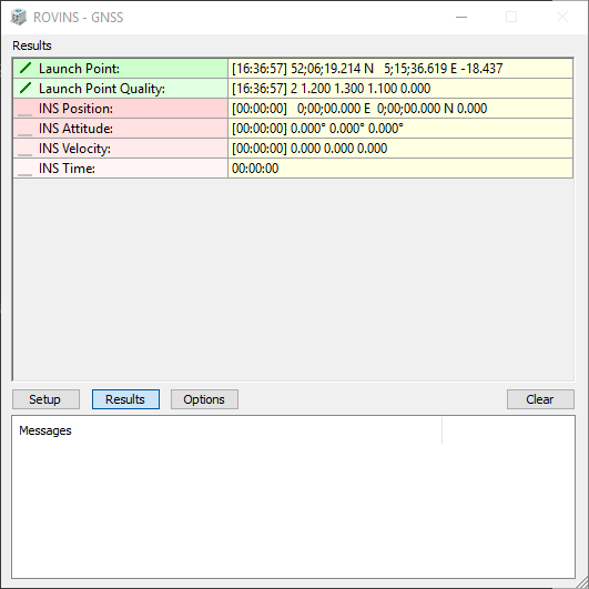
Example sending Launch Point position |
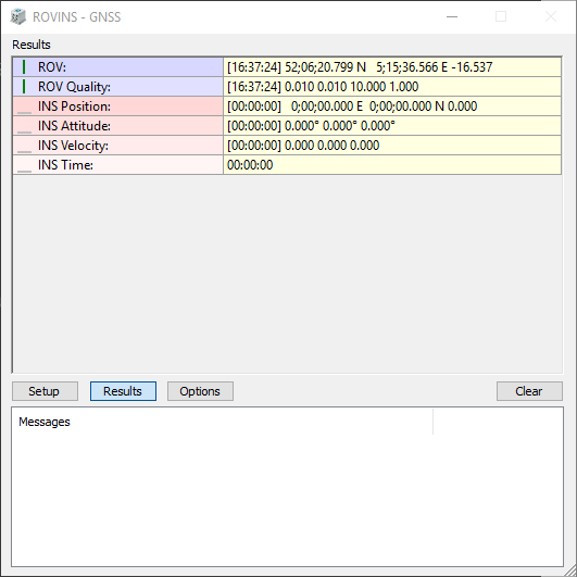
Example sending ROV position |
|---|---|
|
|
Info
Note that either Launch Point or ROV data is shown based on which message is sent to the INS.
Launch point data is shown when GPS data is sent to the INS, ROV data is shown when USBL data is sent.
Output
|
Launch Point / ROV: |
The last encoded position for the selected Launch Point Node which will be outputted. Displayed are the [Update Time], Latitude, Longitude and height.
|
|---|---|
|
Launch Point / ROV Quality: |
The last encoded quality figures. Displayed are quality, latitude SD, longitude SD, height SD, latitude/longitude covariance. |
Input
|
INS Position: |
The last decoded position data from the position data block. Displayed are the [Update Time], Latitude, Longitude and height.
|
|---|---|
|
INS Attitude: |
The last decoded attitude data from the Attitude & Heading data block. Displayed are the [Update Time], the Heading, Pitch and Roll. |
|
INS Velocity: |
The last decoded three axis velocity data from the Speed data block in vessel frame. Displayed are the [Update Time], Velocity XV1, XV2 and XV3. |
|
INS Time: |
The last decoded time information from the extUTC data block. Displayed is the UTC time. |
Driver Layout Menu: Options
|
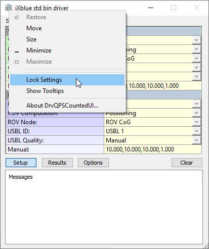
Lock Settings |
Enables locking the user-interface settings of the Setup and Options menu, in order to prevent making changes by mistake.
|
|---|---|
|
Show Tooltips |
When hovering the mouse over the left column rows, you will get some more information. Disable if this becomes annoying...
|
|
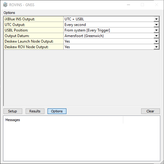
iXblue INS Output: |
|
|
UTC Output: |
Select the desired output update rate for the UTC message. Output of this message can only be triggered on time. Every second is recommended. |
|
GPS Output: |
Select the desired output update rate for the GPS message. Output of this message can only be triggered on time.
|
|
USBL Position: |
Select the desired output update rate for the USBL message. The output rate is defined as a fraction of the update rate of the computation was chosen in the setup. Optionally, a 'maximum age' can be used. If this option is selected, the last sent USBL position will be resent if the maximum age expires before a new result has been computed. |
|
Max age |
Only available when 'From system [every trigger + max age]' is selected under 'USBL position'
|
|
Output datum |
By default this would be on source datum (normally WGS'84). With this option the user may force the outputted position to be on Survey datum. |
|
Deskew Launch Node Output: |
Select Yes in order to skew the time and position of the launch point node to the time of output (GPS message), using the current SOG and COG. Note that the SOG and COG depend on the Controller's Computation Setup, Object COG/SOG - Prediction Parameters Settings. The height value is not deskewed. |
|
Deskew ROV Node Output: |
Select Yes in order to skew the time and position of the ROV node to the time of output (USBL message), using the current SOG and COG. Note that the SOG and COG depend on the Controller's Computation Setup, Object COG/SOG - Prediction Parameters Settings.
|
Dialog Buttons
|
Setup |
Invoke the Setup Menu |
|---|---|
|
Results |
Invoke the Results Menu |
|
Options |
Invoke the Options Menu |
|
Clear |
Will clear the messages displayed below.
|
Hiding user interface
Click to expand...
It is possible, once the driver is set up or when no output is required to hide the user interface.
The option to do this can be found here:
-
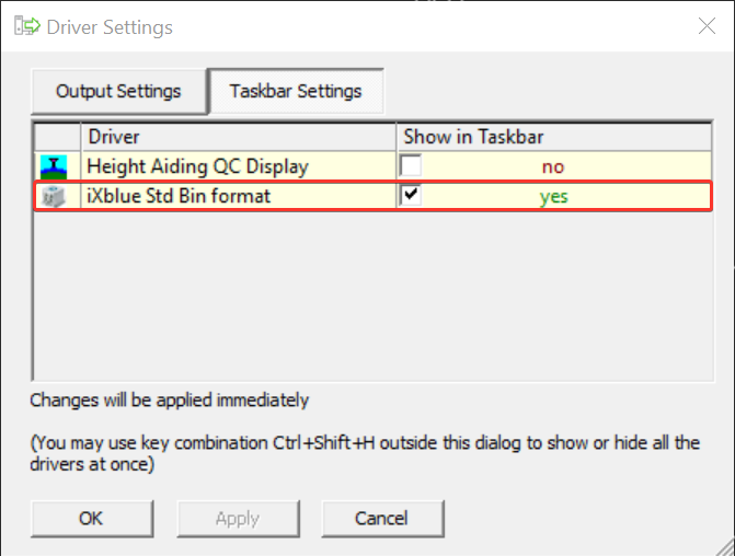
Open the "Driver Settings" from the Qinsy Controller
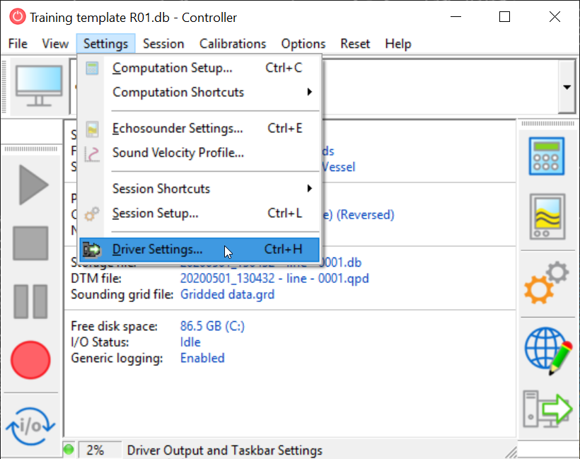
-
Then with the checkbox you can hide it
Also, if you are just using the driver to decode information and not to output to an INS, you can hide the UI.
Display - Generic
Click to expand...
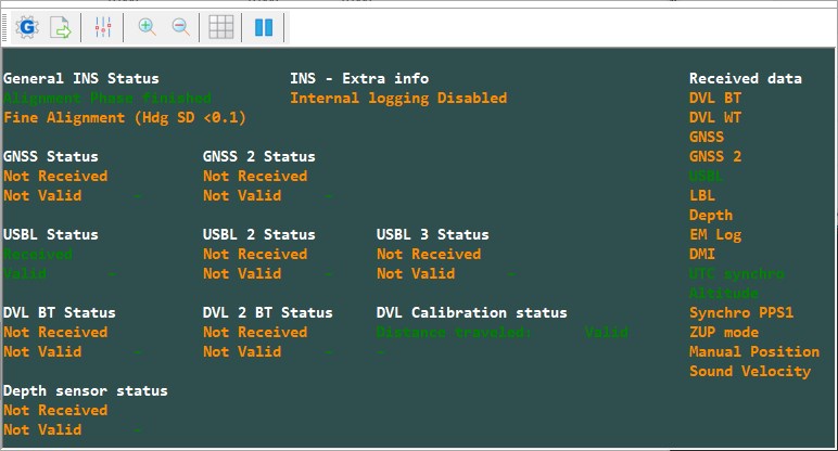
|
Received |
Data is sent in the correct format and is decoded. |
|---|---|
|
Valid |
The decoded data is accepted by the algorithm and is also being used by the algorithm. |
|
Waiting |
No data received. |
|
Rejected |
The decoded data is not accepted by the algorithm and therefore not used by the algorithm. |
You can download the above display example XML here: iXblue - Std Bin format - Status.xml
-
Add a Generic Display
-
Open the above XML
Note that you need to add the following miscellaneous observations to decode these:
-
To your Template:
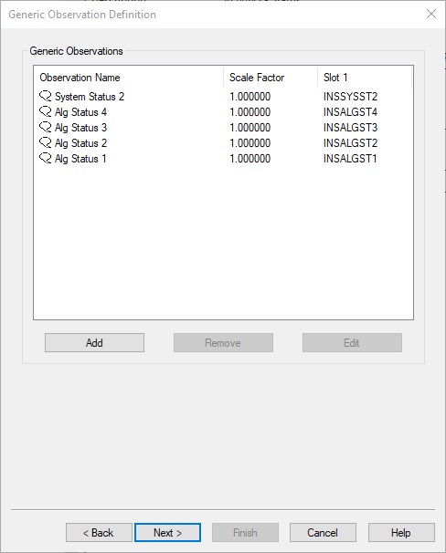
-
To the Generic Layout Editor when Online:
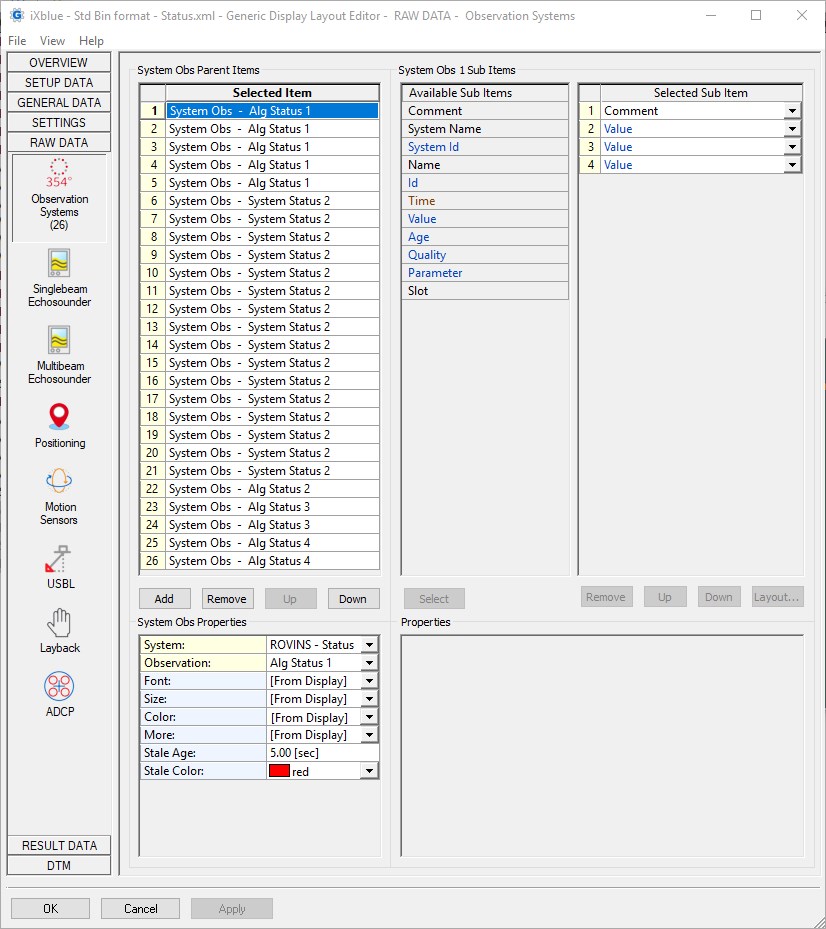
Adding extra items
In case you want to add more items yourself you'll need the iXblue manual and take the following steps:
-
Go to Raw Data → Observation Systems
-
Add
-
Check the iXblue manual on what you want to decode and in which message it can be found
-
Select the same one here
-
Add a Value item
-
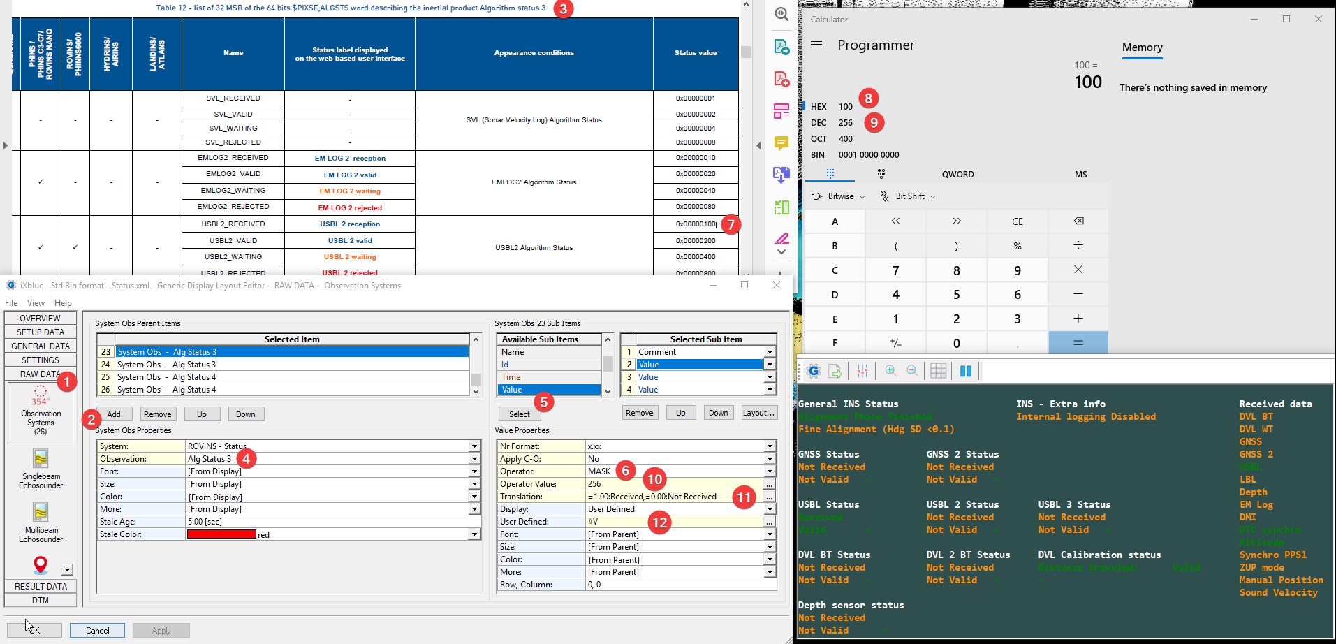
Add a mask for Operator
-
Check what the Status value is
-
Open a Programmer calculator and enter it as a Hexadecimal value
-
Check what the corresponding Decimal result is
-
Enter this as Operator Value
-
Add a Translation, example below:
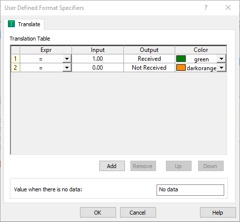
Result will either be 0.00 or 1.00.
-
Select on what you would like to show.
Viewing ARPA targets
Click to expand...
In order to view any LBL or USBL beacon as an ARPA target a Navigation Display must be added.
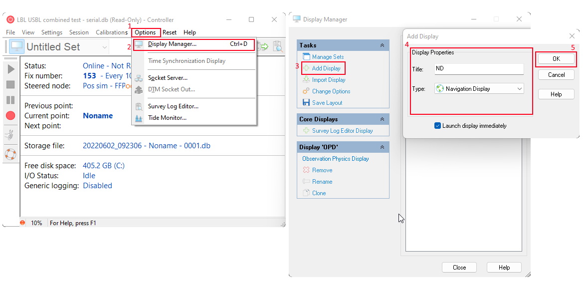
-
Adding the navigation display can be done through Options on the menu bar
-
Press Display Manager...
-
Within the Display Manager, a display can be added using the Add display option.
-
Give it an appropriate title and select
-
Press OK to add it.
In order to see these targets the navigation display may need additional configuration
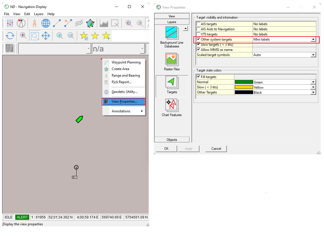
-
Within the navigation display right click anywhere in the display to open up the context menu and press View Properties...
-
Within the properties navigate to Layers > Targets and make sure to have Other system targets ticked.