Innovatum Smartsearch Gradiometer - 35
Description
This driver can be used to decode the magnetic field gradient values from an Innovatum SMARTSEARCH gradiometer system.

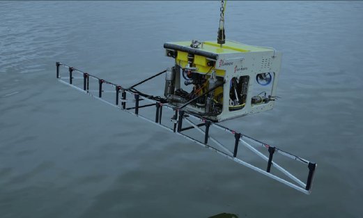
SMARTSEARCH is an underwater survey system providing highly detailed magnetic mapping both in marine
and land environments. SMARTSEARCH consists of an array of very sensitive magnetic gradiometers which measure magnetic field gradients in the vertical (Z) plane. The normal ROV array has 3 sensors, with expansion available up to 12 sensors.
Driver Information
Driver | Innovatum Smartsearch Gradiometer | Interface Type | Serial | Driver Class Type | Terminated |
|---|---|---|---|---|---|
No | Input / Output | Input | Executable | DrvNavitronic.exe | |
Related Systems |
| ||||
Related Pages | |||||
Decoding Notes
Due to many reasons the magnetometer values are handled within Qinsy in a special manner:
The SMARTSEARCH outputs the gradient values in nanoTesla. The driver divides (hard coded) by 1000 in order to convert to microTesla. So all gradient values in database and (raw) displays are in microTesla. In the sounding grid also the value is in microTesla. In the QPD the values are represented as NanoTesla again. When exporting from QPD the values will also be in nanoTesla.
Time of arrival minus the latency is used as the measuring time of the sensor. Example data shows that the latency value as reported by the SMARTSEARCH is always zero. The gradient values are decoded and divided by 1000 (converted from nanoTesla to microTesla) as the magnetometer observation, the quality figure as its quality. The slot number of the magnetometer is used to link the value/quality from the string to the defined system, for example the left most value is decoded and assigned to the Magnetometer system with slot number "1". The Right most value is decoded and assigned to the Magnetometer system with slot number "12".
Database Setup
In the setup for every SMARTSEARCH sensor stick a node offset should be defined first. The sensors are usually placed in a line array with a fixed distance between the sensors.
Add a new System of the type "Magnetometer" and select Driver "Innovatum Smartsearch Gradiometer". Select the proper serial port and COM parameters. On the next page select the Object on which the sensor is mounted and the node offset location. Also enter the slot number of the sensor, this should be a value between 1 and 12 (see Decoding notes).
Repeat the step above for all the sensors until every sensor is represented by a Magnetometer System. Make sure to select the same port number and COM parameters for every system.
Online
The field gradients can be stored in the QPD DTM file and/or in a sounding grid. The sounding grid will not be filled completely but instead for each sensor a "track" will be filled with the sensor data similar to a single beam echo sounder track. The Sounding Grid Utility program can be used to fill the empty cell grids in between the "tracks" by interpolation. Different methods can be selected but in this case the "DIGIPOL" interpolation will lead to very good results as this is an optimized algorithm for single beam surveys.
Additional Information
Database Setup
Add manual echosounder
Please be aware that you need to add a Manual echosounder to your towed object to be able to process the track of the towed object.
Online / Replay
Since Qinsy version 8.10.2014.10.20:
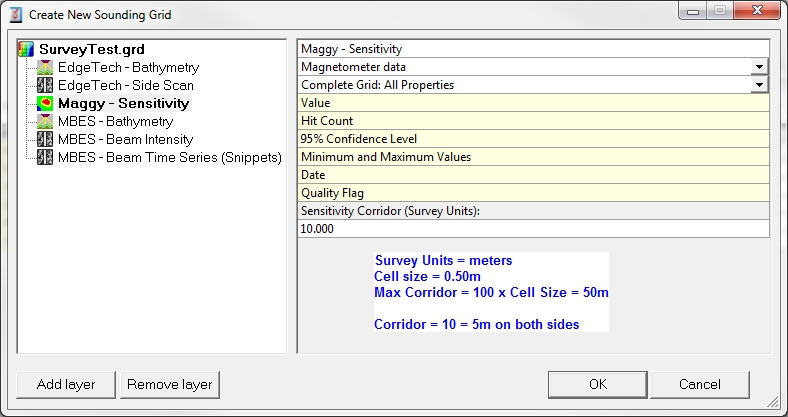
Storing magnetometer data to a sounding grid has the option to create a corridor perpendicular to the sailing direction. I.e. that the full path of the corridor is filled automatically with each single reading of the magnetometer. To set this corridor width value, go to the layer properties in the Controller Session Setup, Storage, Sounding grid or use the Sounding Grid Utility, making sure that the layer type is 'Magnetometer data'. The maximum width of the corridor is 100 times the minimum cell size of the sounding grid

