
Description
Driver to decode data from an Innovatum magnetic submarine cable and pipeline detection system
Driver Information
|
Driver |
Innovatum SMARTRAK cable tracking |
Interface Type |
Serial |
Driver Class Type |
Terminated <LF> |
|---|---|---|---|---|---|
|
No |
Input / Output |
Input |
Executable |
DrvInnovatum.exe |
|
|
Related Systems |
|
||||
|
Related Pages |
|
||||
Database Setup
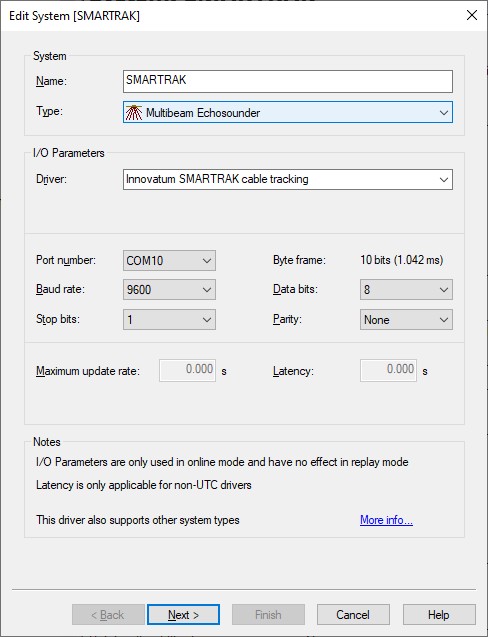
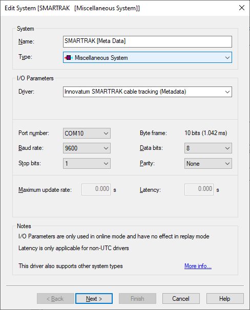
Important is to use the same interfacing settings for all 'Innovatum SMARTRAK cable tracking' systems in your template setup. These interface settings should be defined on every first wizard page.
Add a Multibeam Echosounder System to your template setup and select driver "Innovatum SMARTRAK cable tracking".
Of course SMARTRAK data is not real multibeam data but the in real-time detected cable or pipe can be decoded as beam XYZ results and therefore stored as points with absolute co-ordinates in a DTM point processing file (QPD).
Note that a future version release of Qimera (2.4.0 and newer) will have enhanced functionality for processing the cable track using all necessary information from the data output string.
This functionality will skip the need for using third party processing software using all kind of single generated and/or exported ASCII files with information gathered from different sources.
-
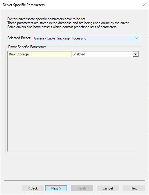
Raw Storage
Enable the setting so all data from the SMARTRAK will be preserved and ready to use within (that future version of) Qimera. Note that enabling this setting will increase the file size of each recorded database slightly.
At time of writing this document the cable/tracking processing functionality isn't yet available in Qimera. It will be available in Qimera 2.4.0.
-
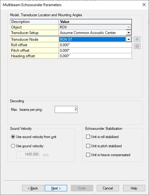
Select the correct Transducer Node location.
Normally this will be the node location (center of array) of the SMARTRAK unit mounted on the ROV. -
Set the Max. beams per ping: 2
The XYZ values of these two beams will be decoded as follows:
|
Beam |
X |
Y |
Z |
|---|---|---|---|
|
1 |
Horizontal Displacement |
0.0 |
Vertical Displacement |
|
2 |
Horizontal Displacement |
0.0 |
Skids To Top |
-
Where:
-
Horizontal Displacement will be the Horizontal displacement of the detected target: from center of array to center of target.
-
Vertical Displacement will be the Vertical displacement of the detected target: from Reference to center of target.
-
Skids To Top can be:
-
Vertical displacement from skids to top of detected target which equals "depth of bury" but ONLY if vehicle skids are level with seabed.
OR -
Burial ("depth of bury") but ONLY if altimeter option is both installed and enabled.
-
-
All units in meters.
-
Y value will always be zero.
-
-
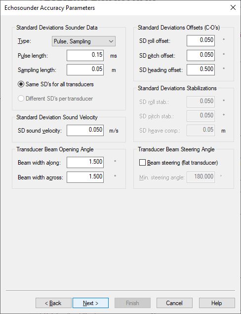
You may leave all parameters at their defaults
-
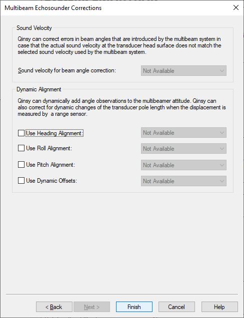
You may leave all parameters at their defaults
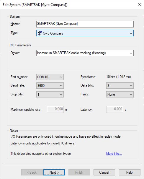
Add a Gyro Compass System to your template setup and select driver "Innovatum SMARTRAK cable tracking (Heading)".
The absolute heading will be decoded which can be from the system's own flux gate compass or from an external gyro compass sensor.
Note that this heading field is only available in the long data output string format.
Of course when the external gyro compass sensor is also interfaced directly into Qinsy then there is no need to add this system, but for analyzing purposes it may be useful.
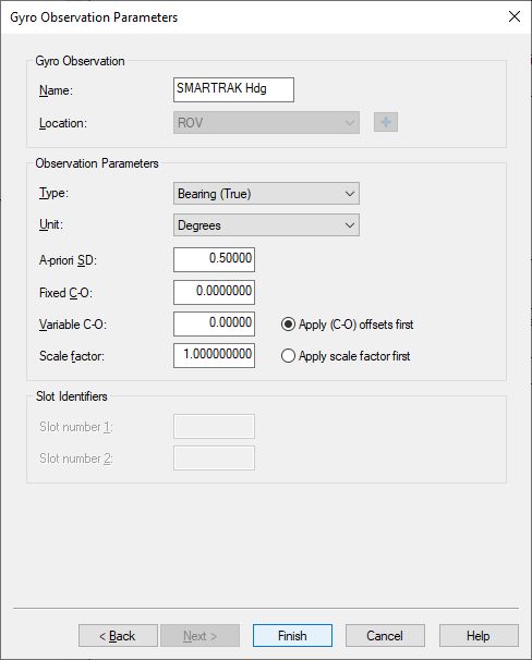
-
You may leave all parameters at their defaults
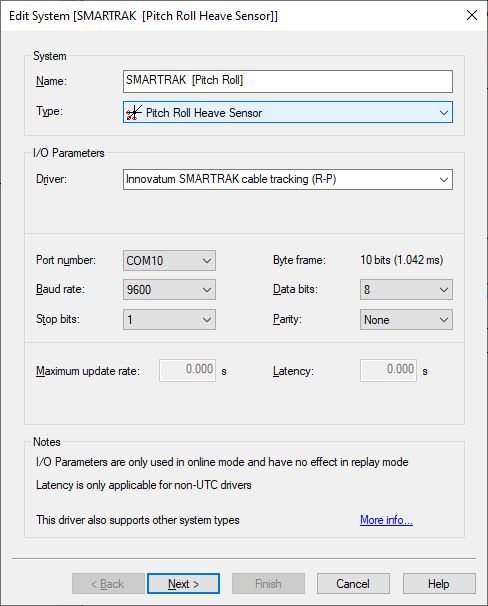
Add a Pitch Roll Heave Sensor to your template setup and select driver "Innovatum SMARTRAK cable tracking (R-P)".
The roll and pitch value will be decoded which are available in the long data output string format. Note that there is no heave value in the data output string message.
When the same motion sensor is also interfaced directly into Qinsy then there is no need to add this system, but for analyzing purposes it may be useful.
-
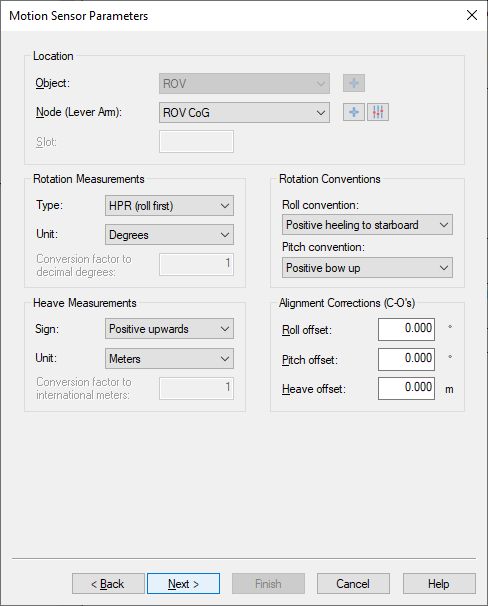
Select the correct Node location.
Normally this will be the node location (center of array) of the SMARTRAK unit mounted on the ROV. -
Leave the sign conventions at their defaults: roll positive heeling to starboard, pitch positive bow up.
-
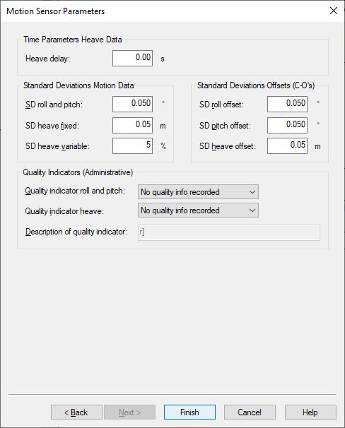
You may leave all parameters at their defaults
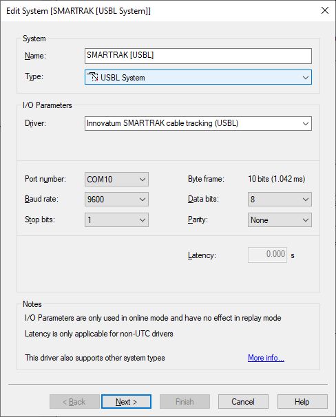
Add a USBL System to your template setup and select driver "Innovatum SMARTRAK cable tracking (USBL)".
The in real-time detected cable or pipe can be decoded as USBL XYZ observations and therefore absolute coordinates can be retrieved from the node results.
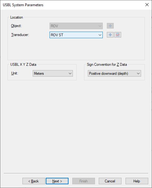
-
Select the correct Transducer location.
Normally this will be the node location (center of array) of the SMARTRAK unit mounted on the ROV. -
Leave the unit to Meters and the Z sign convention positive downwards (depth).
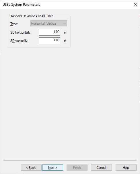
-
You may leave all parameters at their defaults
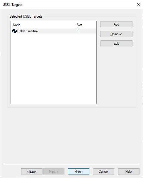
It is recommended to have a dedicated object that represents the USBL derived cable track present in your template setup.
-
Use the Add button and select the CoG node of the dedicated object.
The Slot 1 ID should be '1' (decode the Vertical Displacement as USBL Z value) or '2' (decode the Vertical Displacement as USBL Z value).
|
Slot 1 ID |
USBL X |
USBL Y |
USBL Z |
|---|---|---|---|
|
1 |
Horizontal Displacement |
0.0 |
Vertical Displacement |
|
2 |
Horizontal Displacement |
0.0 |
Skids to Top |
-
Where:
-
Horizontal Displacement will be the Horizontal displacement of the detected target: from center of array to center of target.
-
Vertical Displacement will be the Vertical displacement of the detected target: from Reference to center of target.
-
Skids To Top can be:
-
Vertical displacement from skids to top of detected target which equals "depth of bury" but ONLY if vehicle skids are level with seabed.
OR -
Burial ("depth of bury") but ONLY if altimeter option is both installed and enabled.
-
-
All units in meters.
-
Y value will always be zero
Note that you can always change the Slot Id while online using the Controller's Computation Setup, but you could also setup and add two targets here: each one with its own dedicated Slot 1 ID. -
Add a Magnetometer System to your template setup and select driver "Innovatum SMARTRAK cable tracking (Magnetic)".
This will decode the Magnetization value from the data output string as magnetic observation which can be stored to a DTM processing file (QPD).
Note that the original value is in nano Tesla (nT) but the driver will convert this to micro Tesla (uT) so the value will be stored in recorded database as uT.
The quality value of the magnetic observation will be the decoded Signal Strength value from the data output string.
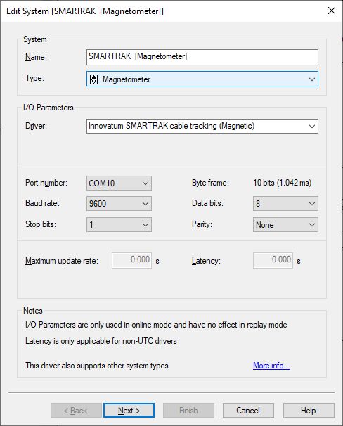
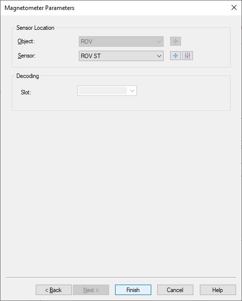
-
Select the correct Sensor location.
Normally this will be the node location (center of array) of the SMARTRAK unit mounted on the ROV
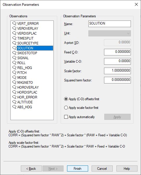
Add a Miscellaneous System to your template setup and select driver "Innovatum SMARTRAK cable tracking (Metadata)".
Generic observations will be decoded for every available field of the data output string.
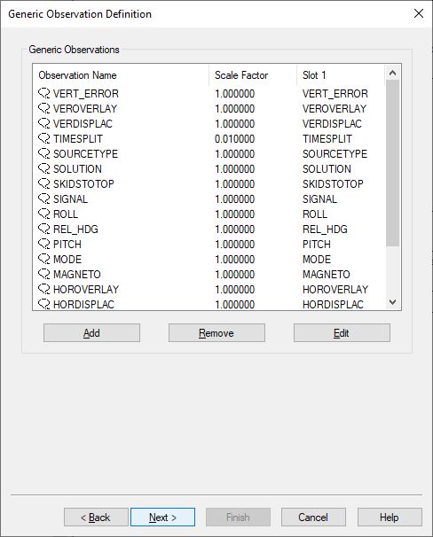
-
Here you can add up to eighteen generic observations that you may want to monitor.
Each generic observation needs a unique Slot Id so the driver knows which field to decode.
It is highly recommended to use the drop-down selection for the correct Slot Id:
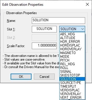
Of course you may change the default name for each observation as long as it doesn't exceed 16 characters.
|
Field |
Slot 1 |
|---|---|
|
Relative Heading |
REL_HDG |
|
Mode |
MODE |
|
Solution |
SOLUTION |
|
Signal Strength |
SIGNAL |
|
Horizontal Overlay |
HOROVERLAY |
|
Vertical Overlay |
VEROVERLAY |
|
Source Type |
SOURCETYPE |
|
Horizontal Displacement |
HORDISPLAC |
|
Horizontal Error |
HOR_ERROR |
|
Vertical Displacement |
VERDISPLAC |
|
Vertical Error |
VERT_ERROR |
|
Skids To Top |
SKIDSTOTOP |
|
Magnetization in nT |
MAGNETO |
|
Altitude |
ALTITUDE |
|
Pitch |
PITCH |
|
Roll |
ROLL |
|
Absolute Heading |
ABS_HDG |
|
Timesplit |
TIMESPLIT |
|
Sensor Array being used |
ARRAY |
|
Spare |
SPARE |
|
Left Sensor reading in nT |
LEFTSENSOR |
|
Center Sensor reading in nT |
CENTSENSOR |
|
Right Sensor reading in nT |
RGHTSENSOR |
|
Format Version number |
VERSION |
The blue fields are not available in the short format of the data output string.
The yellow fields are only available in the extended format of the data output string (V2 or higher).
Note that Slot ID value are case-sensitive.
-
Here you can also change the default name of each observation as long as it doesn't exceed 16 characters.
You may leave all parameters at their defaults.
Decoding Notes
-
Driver "Innovatum PipeTracker" will only decode data and pass it onto the rest of Qinsy when the decoded Solution is either 2 (Valid horizontal displacement only) or 3 (Valid horizontal and vertical displacements)
-
If you do not want to validate the data first using the Solution, select driver "Innovatum PipeTracker (Ignore Solution Mode)". In this case data will always be decoded and passed onto Qinsy, regardless of the decoded solution value.
-
The Beam Quality, Heading Quality, Pitch Quality and Roll Quality value will be the decoded Solution value.
-
The Beam Intensity value will be the vector of the horizontal and vertical probable maximum error in meters.
-
Both Vertical displacement values are only decoded when the Solution is 3 (Valid horizontal and vertical displacements). Otherwise Beam Z will be zero.