
Description
The International Marine Contractors Association has outlined a standard protocol (IMCA S 006) for inter-vessel data telemetry.
The purpose was to define a standard for position and supplement data transfer between vessels involved in survey operations using different navigation software packages.
The standard defines a so-called Generic Message and an Anchor Spread Message . This input driver handles the decoding of the IMCA Anchor Spread Message format.
Notice that decoding of the IMCA Generic Message is explained in the IMCA Generic Message documentation under Position Navigation System Drivers.
Driver Information
|
Driver |
IMCA Anchor Spread Message |
Interface Type |
Serial |
Driver Class Type |
Terminated |
|---|---|---|---|---|---|
|
No |
Input / Output |
Input |
Executable |
DrvIMCA.exe |
|
|
Related Systems |
|||||
|
Related Pages |
|||||
Decoding Notes
Decoded anchors will be handled as so-called remote anchors. This means that a Qinsy user has no control over these anchors. Remote anchors are used purely for visualization, and can be made visible using a Navigation Display.
In order to do so, enable the option "Show remote anchors", under View Properties, Group Anchors Layers.
All displayed remote anchors in Navigation Display will have a ®-character behind their names.
The driver also supports decoding data types from IMCA Generic Messages. Please see the IMCA Generic Message documentation under Position Navigation System Drivers.
Note that limited information is received in the Anchor Spread Message. For example only the name of an anchor and its current location. No additional information, like distance/bearing from/to an assigned tug or rig can be given or calculated.
From the IMCA S 006 documentation the following: "...It is intended that all packages should conform to level 1 and that levels 2 and 3 be used as the basis for development when required by project requirements.".
So maybe in the future IMCA allows more information to be available in the Anchor Spread message (which is part of Level 3).
However, if on the same COM port an IMCA Generic Message is received with the position and heading of the involved rig object (in the example below the Noble Linda Bossler), then for each anchor a range/bearing will be calculated between the rig winch node and the dropped anchor location.
See for more information about this the tab page Qinsy Config - Database Setup.
Interfacing Notes
The driver is a so-called passive driver, i.e. it does not send commands or data back to the sensor.
Therefore only a one-way cable wiring is needed.
One-way Cable wiring diagram:
|
DB-25 |
Sensor |
or |
DB-9 |
Sensor |
|
DB-25 |
COM |
or |
DB-9 |
COM |
|---|---|---|---|---|---|---|---|---|---|---|
|
Pin 2 |
TXD |
|
Pin 3 |
TXD |
----- |
Pin 3 |
RXD |
|
Pin 2 |
RXD |
|
Pin 3 |
RXD |
|
Pin 2 |
RXD |
X |
Pin 2 |
TXD |
|
Pin 3 |
TXD |
|
Pin 7 |
SG |
|
Pin 5 |
SG |
----- |
Pin 7 |
SG |
|
Pin 5 |
SG |
Database Setup
In order to decode remote anchors from the IMCA Anchor Spread Message, add a Miscellaneous System to your template and select the driver "IMCA Anchor Spread Message".
Add on the 2nd wizard page a generic observation, name it 'Anchor Count', and important, set the slot1 id to 'ANC'. (Leave the scale-factor to 1.0, it won't be used.)
Note.
To decode remote anchors, it is important to enter the right 'Slot Id':
|
Generic Observation |
Slot Id |
|---|---|
|
Anchor Count |
ANC |
Normally only the status of the anchor (blue when dropped, green when running, yellow when racked) and its current location (dropped location when dropped, tug position when running, rig position when racked) will be displayed.
Connection for winch
In order to show a range/bearing marker in the Navigation Display between a dropped anchor and the rig winch node, you must also receive the position and heading for the rig, via an IMCA Generic 'PH' Message on the same COM port.
Further, you must define in your Database Setup this rig object, and importantly, each defined winch node on this object must be named exactly as the received anchor names.
So in the above example data you must have defined an object, called "Noble Linda Bossler", containing two nodes, called "Stern Port" and "Stern Stbd".
See the IMCA Generic Message documentation for more information about setting up a Positioning and Heading system for this rig object.
IMCA Generic 'PH' Message
Some notes on this message in case you generate it yourself:
|
Item |
Notes |
|---|---|
|
Object Name |
Should be the same as in the Qinsy template. |
|
Object Heading |
True heading. |
|
Object Position
|
Latitude and Longitude should be WGS '84. |
|
Position should be valid for the CoG location (common reference point) that is setup in the Qinsy template. |
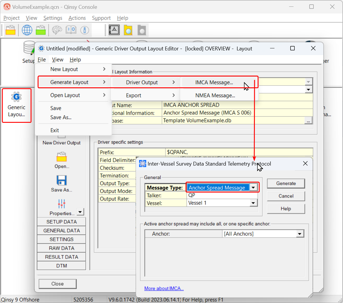
If you want to Output the IMCA anchor spread, you need to create a generic driver:
Online
The user may also enable view setting "Anchor Status Information" in the Navigation Display.
Color codes for the anchors are:
|
IMCA message |
QINSy Anchors |
||
|---|---|---|---|
|
Name |
Value |
Status |
Color |
|
UNSPECIFIED |
0 |
Free |
White |
|
RACKED |
1 |
Racked |
Yellow |
|
RUNNING |
2 |
Transit |
Green |
|
ON BOTTOM |
3 |
Dropped |
Blue |
The number of received anchors can be viewed in an Observation Physics Display.
Select the generic observation Anchor Count.
Drivers IO Notes
Command line parameter description for "drivers.io" file.
By default the data string checksum is used to check the integrity of the received data.
Cmdline parameter 'NOCS' will disable this checking of the checksum.
Of course, this cmdline option is not recommended to use, but might be used in very rare occasions.
Additional Information
References: IMCA S 006 Rev.1 2003