
Description
Driver for decoding a Honeywell PLC Output string.
This is a format which can be expected on hopper dredging vessels, using a Honeywell PLC.
The ASCII data string contains, among other things, a tide value, draft sensor values, depth sensor values and a geographical position.
Besides decoding these observation types, the driver is capable of calculating a pitch angle for the underwater pipe object, using the values of the two depth sensors.
Of course, these sensors should be mounted on the pipe object.
From Qinsy v9.2.0 on the driver will automatically support the so-called Wartsila PLC Output string .
This string is a modification of the original Honeywell string: most fields are the same but the Wartsila string is longer and has additional observation values.
Driver Information
|
Driver |
Honeywell PLC |
Interface Type |
Serial |
Driver Class Type |
Terminated |
|---|---|---|---|---|---|
|
No |
Input / Output |
Input |
Executable |
DrvQPSTerminated.exe HONEYWELL_PLC |
|
|
Related Systems |
|
||||
|
Related Pages |
|
||||
Qinsy Config
Database Setup
The I/O Interface parameters must be the same as for all above defined systems.
Tide Gauge
-
In order to decode the tide value add a Tide Gauge system to your template setup and select driver "Honeywell PLC (Tide)".
On the 2nd wizard page, add a (virtual) tide station and leave the observation parameters of the last wizard page at the default ones.
The driver will automatically convert the 'tide + 100cm' value to survey units.
Underwater Sensor
-
In order to decode the forward and aft draft value add an Underwater Sensor system to your setup and select driver "Honeywell PLC (Draft/Depth)".
On the 2nd wizard page add two observations of type 'Draft', select the corresponding node and set the correct Slot using the value from the table below.
Additionally you may add a third 'Draft' type observation which will return the mean value of the decoded forward and aft draft value.
Leave the observation parameters on the last wizard page at their defaults.The driver will automatically convert the 'draft pressure' to survey units.
It is important to enter the Slot Id's using capitals.
|
Field |
Description |
System |
Observation |
Slot ID |
|---|---|---|---|---|
|
BBB |
Aft draft pressure |
Underwater Sensor |
Draft |
AFT |
|
CCC |
Fwd draft pressure |
Underwater Sensor |
Draft |
FWD |
|
|
Aft+ (Fwd-Aft) / 2 |
Underwater Sensor |
Draft |
MEAN |
-
Use the same Underwater Sensor to decode the draghead and gymbal depth sensor values.
On the 2nd wizard page add two observations of type 'ROV Depth', select the corresponding node and set the correct Slot using the value from the table below.
Leave the observation parameters on the last wizard page at their defaults.
The driver will automatically convert the 'depth+100cm' to survey units.
It is important to enter the Slot Id's using capitals.
|
Field |
Description |
System |
Observation |
Slot ID |
|---|---|---|---|---|
|
FFFF |
Draghead water depth + 100 cm |
Underwater Sensor |
ROV Depth |
DRAGHEAD |
|
GGGG |
Intermediate water depth + 100 cm |
Underwater Sensor |
ROV Depth |
GYMBAL |
Pitch Roll and Heave Sensor
-
In order to get the calculated pitch from the two depth sensors add a Pitch Roll and Heave Sensor system to your setup and select driver "Honeywell PLC (Pitch)".
Important
On the 2nd wizard page you must use the Slot number field to fill in the distance between the two depth sensors on the pipe object in cm's.
For example enter "853" when the distance between the two depth sensors on the pipe is 8.53 m.
-
Leave the other Motion Parameters to defaults, except for the Pitch convention. This should be set to 'Positive bow down' (but it may depend on how the suction pipe object is defined).
Note that when the pipe is laying horizontally in the water (i.e. both depth sensors have the same value) the pitch value will be zero.
When the pipe hangs all the way down the pitch will be 90°.
So under normal working conditions, the driver will calculate a positive pitch value between 0 and 90°.
Position Navigation System
-
In order to decode the position add a Position Navigation system to your setup and select driver "Honeywell PLC (Lat/Lon)".
Note that the latitude and longitude field is only available in the original Honeywell PLC output string and not in the Wartsila output.
A height value is never available.
Dredging Sensor
-
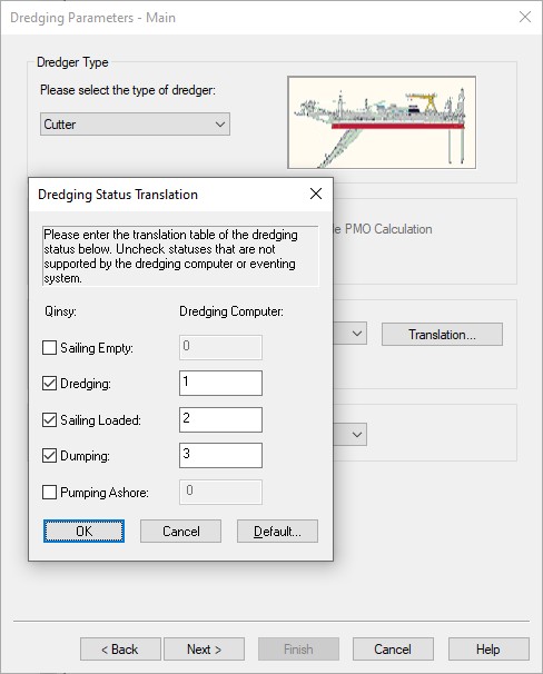
In order to decode the dredge status field, add a Dredging Sensor system to your setup, and select driver "Honeywell PLC (Dredge Status)".
Add an observation of type 'Status' and leave the observation parameters at their defaults.
Additionally, when a Dredging System has been added to the template setup, you can now select on the 2nd wizard page the newly added Status observation.
You may set the Dredging Status Translation as follows:
The Wartsila PLC output string has more dredging related observations to be decoded which are not available in the original Honeywell output.
So in that case add in the same Dredging Sensor a Density, Weight, Volume, Mixture Velocity and Hopper Level observation next to the Status:
|
Field |
Description |
System |
Observation |
Slot ID |
|---|---|---|---|---|
|
J |
Dredge status (1=dredging, 2=sailing, 3=dumping, 4=bucket) |
Dredging Sensor |
Status |
n/a |
|
KKK |
Dredge pump Load (kW) |
Dredging Sensor |
Weight |
n/a |
|
MMM |
Spoil Flow Rate (m/sec) |
Dredging Sensor |
Mixture Velocity |
n/a |
|
NNNN |
Mud Volume (m3) |
Dredging Sensor |
Volume |
n/a |
|
OOOO |
Average density (kg/m3) |
Dredging Sensor |
Density |
n/a |
|
PPP |
Hydraulic Pump Pressure (bar) Pump1 + Pump 2 |
Dredging Sensor |
Hopper Level |
n/a |
-
The driver will automatically convert the values from the string to survey units.
Miscellaneous System
-
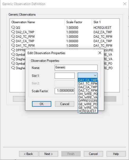
In order to decode all other available fields (e.g. the wire payout and wire vertical angle value) add a Miscellaneous system to your setup and select driver "Honeywell PLC (Wire Payout/Wire Angle)".
These values will be decoded as generic observations.
On the 2nd wizard page add for each field that you want to decode a generic observations and use the selection from the drop-down box to set the correct Slot ID.
Of course you may overrule the name of the observation for better clarity.
|
Field |
Description |
System |
Observation |
Slot ID |
|---|---|---|---|---|
|
DDDD |
Draghead wire payout in cm. |
Miscellaneous System |
Generic |
DH_WIRE_PO |
|
EEEE |
Intermediate wire payout in cm. |
Miscellaneous System |
Generic |
GB_WIRE_PO |
|
HHHH |
Draghead wire encoder vertical angle in degrees (90=vertical) |
Miscellaneous System |
Generic |
DH_WIRE_VA |
|
IIII |
Intermediate wire encoder vertical angle in degrees (90=vertical) |
Miscellaneous System |
Generic |
GB_WIRE_VA |
|
LLL |
Dredge Pump Vacuum Pressure (kPa) + 100 |
Miscellaneous System |
Generic |
DPPRESSURE |
|
|
Hydraulic Control request (0=No, 9= Hull Operations,10=Windlass/Winch Operations, 11=Dredge Operations) |
Miscellaneous System |
Generic |
HCREQUEST |
|
RRRRR |
DA_1_TC_RPM |
Miscellaneous System |
Generic |
DA1_TC_RPM |
|
SSSSS |
DA_2_TC_RPM |
Miscellaneous System |
Generic |
DA2_TC_RPM |
|
TTT |
DA_1_Cylinder_Average_Temperature |
Miscellaneous System |
Generic |
DA1_CA_TMP |
|
UUU |
DA_2_Cylinder_Average_Temperature |
Miscellaneous System |
Generic |
DA2_CA_TMP |
-
Fields LLL - UUU are only available in the Wartsila output string. The Slot Id's are case sensitive.
Leave the other parameters at their defaults. The driver will automatically convert the values from the string to survey units and degrees.
Additional Info
Drivers IO Notes
Command line parameter description for "drivers.io" file. Please do not edit this drivers.io file, or only after contacting the QPS Support department.
Cmdline 'HONEYWELL_PLC' tells the driver to expect data from the Honeywell PLC unit.
Cmdline 'NOCS' tells the driver to ignore the checksum of the message.