
Description
Driver to decode the wire lengths and boom angle from the PLC of an Hitachi Sumitomo wire crane.
The driver will calculate the corrected vertical distances from the forward sheave to the grab's upper and lower table and to the tips of the grab shell and output them as USBL observations.
It contains user interface that enables the user to set up the calculation and to perform the calibration of the wire length measurements.
The driver can decode the raw miscellaneous observations, various USBL observations that can be used to position the grab, the grab angle as a pitch observation and a flag observation that indicates if the grab is open or closed.
For more information about how to setup multiple Grab Dimensions see the Additional Info tab.
Driver Information
|
Driver |
Hitachi Sumitomo WireCrane |
Interface Type |
Serial |
Driver Class Type |
Terminated <LF> |
|---|---|---|---|---|---|
|
No |
Input / Output |
Input |
Executable |
DrvQPSTerminatedUI.exe WIRECRANE_HITACHI |
|
|
Related Systems |
|
||||
|
Related Pages |
|
||||
Interfacing Notes
Only a one way serial cable is required from the PLC to Qinsy.
The PLC uses the following serial communication settings: 4800 baud, 8 Databits, No parity bit, 1 Stop bit.
Database Setup
Object Definition
The following objects should be defined in the database:
-
Crane object on which the winches are positioned.
-
Boom object on which the sheaves are located, the pivot point of the boom should be the CoG. The object should be defined in such a way that when the boom lies horizontal, its attitude is zero Heading, pitch, roll.
So the sheaves will have a positive Y coordinate but zero X coordinate, the backward sheave will have a more positive Z offset than the forward sheave. -
Grab objects for the final positioning (with the USBL "to" nodes) ie:
-
lower table object
-
upper table object
-
Shell1 object
-
Shell2 object
-
grab
-
Node Definition
The driver requires the following nodes to be created in the database:
-
Front winch node The crane's forward winch, closest to the boom, offset position should be for the (average) point from where the wire leaves the winch.
-
Back winch node The crane's back winch, closest to the counter weight, offset position should be for the (average) point from where the wire leaves the winch.
-
Front sheave node The boom's sheave that is most forward when boom is vertical or lowest when boom is horizontal, offset position should be of the (average) point where the winch leaves the sheave.
-
Back sheave node The boom's sheave that is most backward when boom is vertical or highest when boom is horizontal, offset position can be somewhere on the perimeter of the sheave and is not so critical.
System Definition
The following systems should be defined in the template:
USBL
Define a USBL system, select Driver "Hitachi Sumitomo WireCrane (dZ)" and define up to 5 observations:
|
Purpose |
Slot String |
|---|---|
|
From front sheave to upper table (only Z) |
UPPER |
|
From front sheave to lower table (only Z) |
LOWER |
|
From front sheave to forward tip (only Y,Z) |
TIP_FORE |
|
From front sheave to aft tip (only Y,Z) |
TIP_AFT |
|
From front sheave to bottom of grab (only Z) |
BOTTOM |
Pitch Roll and Heave Sensor
Define a pitch roll and heave sensor, Select Driver "Hitachi Sumitomo WireCrane (Pitch) and set the same com port parameters as for the USBL system.
The grab angle will be decoded as pitch when slot string GRAB is selected. The boom angle will be decoded as pitch when slot string BOOM is selected.
A boom angle of e.g. 60 degrees will be translated to a pitch of 60 degrees.
|
Purpose |
Slot String |
|---|---|
|
Pitch angle of boom |
BOOM |
|
Pitch angle of tool |
GRAB |
If two shells are to be used and displayed then a Clone driver can be used. Be sure to use the slot GRAB also in the clone driver.
Dredging Sensor Flag observations
Define a dredging sensor, select Driver "Hitachi Sumitomo WireCrane (Grab Open/Close)" and set the same com port parameters as for the USBL system.
Grab Open/close flag
Add a flag observation, it can be used for the grab open close switch required for the grab dredging system. The observation is "0" when the grab is closed and "1" when the grab is opened.
The grab angle is larger than the defined threshold. Slot String should be "OPEN".
Miscellaneous System
Define a Miscellaneous System, select Driver "Hitachi Sumitomo WireCrane (Raw Values)" and set the same com port parameters as for the USBL system.
Add three observations with the following slots:
|
Value |
Slot String |
|---|---|
|
Boom Angle |
BOOM_ANGLE |
|
Front Winch wire Length |
FW_LENGTH |
|
Rear Winch wire Length |
BW_LENGTH |
Online Setup
The database should be set up correctly before going online, see also Qinsy Config.
The driver needs to be set up by the user correctly in order to calculate valid results. When the driver is started for the first time, it will show the crane setup page, here the user should select the computation, the correct objects and the correct nodes for the winches and sheaves. Furthermore, the user should also select the usage of the winches, e.g. if the winch is used for either hoisting the grab or opening and closing the grab. Note that the setup may be modified at all times. The setup is stored in the registry and will be automatically retrieved the next time Qinsy is started. The name of the driver is dependant on the used com port. So if the com port is changed, the settings will not be found anymore and should be re-selected.
The driver shows a message status box that shows the communication progress and a grid control with a variable content depending on which page is selected.
Below the pages are explained further.
Crane Setup Page
On this page the user should select proper computation, objects, nodes and some other settings. If settings are incorrect here, the driver will not calculate correct results!!
Crane, Boom Object
Respectively the object on which the winches and sheaves are located.
Crane boom computation
Select computation for which the node results are taken.
Various Nodes
Select proper nodes.
NOTE: The positions of the nodes need to be as accurate as possible.
Back/Front Winch Purpose
The wires can be rigged to the grab or bucket in various ways. In principle the following combinations are possible:
-
Both hoisting.
The average wire length for both winches is used to calculate the upper table. Lower table will be same as upper, grab angle not calculated. -
One hoisting, one open/close.
The upper table will be positioned with the shortest wire length of the two wire length measurements. The lower table will depend on the difference between the wire measurements. The grab angle is derived via cosine rule from the difference between upper and lower table. -
One hoisting, other not used.
The upper table will be positioned with the selected wire measurement. Lower table will be equal to upper table. Grab angle is not used.
Calibration height
Select whether the calibration is done with a manually entered dtm height or whether the height is taken from any node in the computation. See below for more info on the calibration.
Boom angle C-O
If the boom angle deviates with a fixed offset then it can be entered here.
Used Grab
Select the grab definition of the grab that is currently in use.
Grab Dimensions
Show the grab dimensions as read from the xml file, the K,LMc, Mo,N definitions correspond with the grab drawing above. The driver can not modify the xml settings.
PLC Setup
PLC setup page, here an advanced user can debug the PLC communication. When the PLC is using a two way communication protocol you need to select a request data rate otherwise you have to configure the PLC to output data. When the driver is receiving data the raw decoded values can be monitored for the winches and the boom angle.
The page can be useful in monitoring whether the correct winch is decoded. Note that the driver will automatically request data on startup once configured.
Calibration
On this page the user can quickly (re)calibrate the wire lengths. The currently in use calibration data is also visible (raw wire lengths and open and close time and the used calibration height).
The calibration procedure is pretty straightforward:
-
Close grab and place it on the ground or any other known reference height with the tips closed. You can also zero the wire lengths on the PLC but this is not strictly necessary. Now press the "Calibrate Closed/Height" button, the driver will use the received wire lengths for the calibration data. It will also log the manual or node calibration height for that moment.
-
Open bucket completely, you may touch the hoisting wire, this is not important. Do not modify the boom angle however. Press "Calibrate Open" button. The wire lengths are logged again.
The steps can be carried out in any order, this is not important.
Note that the calibration data is stored in the registry.
Results
On this page the user can witness the results of the calculation.
Calculated Z (Upper Table)
The resulting USBL value, height difference between upper table and the front sheave.
Calculated Z (Lower Table)
The resulting USBL value, height difference between lower table and the front sheave.
Boom Angle
Angle of boom compensated for C-O [degrees]
NOTE: The boom angle is used in the calculation and needs to be accurate. It is recommended to check the correctness of the angle over the working range of the boom.
Grab Angle
Grab opening angle [degrees]. Value will be between 0 degrees (closed) and approximately 90-100 degrees (fully opened).
Hanging from
Either forward or backward winch, if one winch is used for closing the grab it may happen that the grab is hanging on the open/close wire. This field shows which winch has the shortest wire at that moment.
Wire Diff. At grab BW-FW.
Wire difference at the grab, backward minus forward winch.
Cable lengths
Lengths fully corrected for C-O.
Last update shows the time of the last update cycle of the driver.
Locking the User Interface
For preventing accidental setup changes, the surveyor may lock the settings grid. If this option is active, only the calibration can be carried out and no other setting can be modified.
Mouse button click on the icon in the taskbar and a popup menu will be shown. In order to lock the user interface, click on the driver icon in the top left or right corner of the window. One of the menu items is "Lock Settings".
Click it to activate lock and click again to de-active the lock.
Grab dimensions and definitions
The driver automatically creates a grab definition XML file (named "GrabDefinitions.xml") in the Support subfolder of the current project folder if it doesn't already exist.
This file is used to store one or multiple grab definitions. The different grab types can be selected by the user in the setup page.
The grab definition is used in the calibration and calculation, so it is important to select the correct grab. The content of the XML file describes the Grab dimensions, the nomenclature is explained below.
For a correct understanding, the grab definition is explained in the image below:
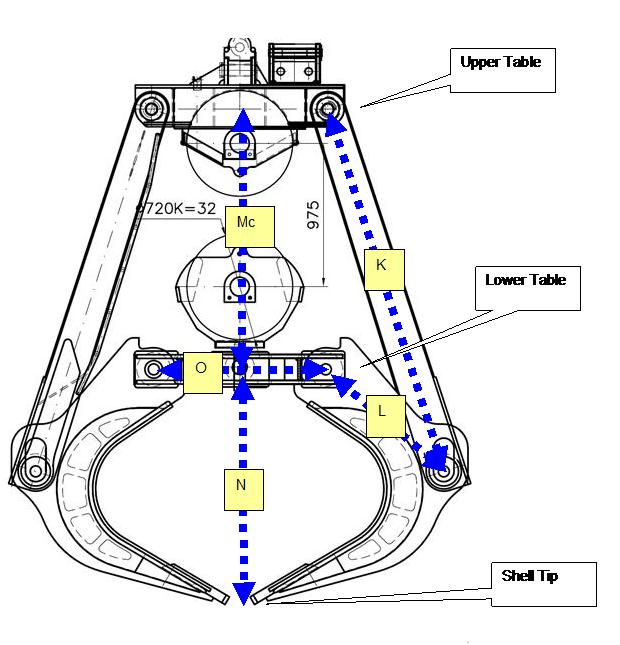
The hoist wire is connected to the Upper Table; the open/close wire to the Lower Table.
The grab definition(s) is (are) read by the driver from an xml file with grab dimensions. This file can not be modified by the driver but should be modified by the user when Qinsy is not started, with a program such as Notepad.
If the file doesn't exist then it will be created by the driver in the Support subfolder of the active project folder with a valid default grab (J&B poliep grijper) on startup.
The following XML tags are used in the xml file:
|
Description |
This is the name that will appear in the combo box in the driver. |
|
UpperTablePivot_To_ShellPivot |
(K) The length of the long arm that connects the Upper Table with the shell. |
|
LowerTablePivot_To_ShellPivot |
(L) The short distance between pivot on Lower Table around which shell rotates and the pivot which connects the long arm to the Upper Table. |
|
UpperTable_To_LowerTable_Closed |
(Mc) Distance from Upper to Lower Table when grab is closed. |
|
UpperTable_To_LowerTable_Open |
(Mo) Distance from Upper to Lower Table when grab is fully opened (Not in image). |
|
LowerTablePivot_To_ShellBottom |
(N) Vertical distance between Lower Table pivot and Shell Tip when grab is closed. |
|
Grab_Opening_Angle_Threshold |
[Degrees] Used for the open close flag. If calculated grab angles become lower than this value, the flag observation will become closed else open. |
|
LowerTable_Pivot_Separation |
(O) Horizontal distance between Lower Table pivot points (used for Shell Tip positioning). |
All dimensions should be in survey units, typically in meters.