
Description
Driver that decodes bathymetry and sidescan data from a GeoAcoustics GeoSwath+ (GS+) Interferometric Sonar System.
This system can be categorized as an enhanced sidescan system that delivers geo-referenced backscatter samples, with multiple transducer groups per head, phase detection and advanced data processing.
An angle can be obtained per sample.
The sonar system broadcasts UDP packets to port 5001 over the network to this driver.
The packets contain:
-
raw angle
-
amplitude
-
travel time per sample
-
quality flag
Driver Information
|
Driver |
GeoSwath Sonar (125/250/500 KHz) |
Interface Type |
UDP |
Driver Class Type |
- |
|---|---|---|---|---|---|
|
Yes |
Input / Output |
Input and Output |
Executable |
DrvGeoSwath.exe |
|
|
Related Systems |
|
||||
|
Related Pages |
|
||||
Coding Notes
Decoding Notes
Within Qinsy each sample is interpreted as a beam. A single swath contains thousands of samples, hence translated into thousands of beams; all beams are stored in the database.
The sonar sends packets of maximum 1024 bytes, therefore for the transmission of one ping a number of packets (e.g. 10) are required.
The driver automatically concatenates the packets to a complete ping before decoding. The sonar system consists of two transducers, both tilted about 30 degrees from vertical, that transmit alternatively.
Note that the mounting angle is not always 30 degrees.
The ping number is incremented every ping.
The time tag from the sonar packets is decoded as the ping time.
Sound velocity used by the sonar is always assumed to be 1500 m/s.; make sure to add an Underwater Sensor system with sound velocity observation to the template for the beam angle correction.
All the samples are decoded as beams.
The sample rate is not reported by the sonar so this should be selected by the user through the Drivers.io options. See below for system configuration.
Data packets
This driver only decodes:
-
swath data
-
sidescan data
-
sound velocity data
Any navigation / attitude / heading data should be interfaced directly into Qinsy and is not decoded by this driver.
Sidescan
The decoded samples are ordered in the time domain and output as a sidescan system. Samples received from the port transducer will be stored in the port channel and from the starboard transducer in the starboard channel. The sidescan decoding is subject to some limitations due to the nature of how sidescan data is stored: if the GS+ system is pinging with two transducers then after the starboard data is received, data from the previous port is merged with it and output as one sidescan ping with two channels. The ping time is averaged between port and starboard ping time. If only one side is pinging then a sidescan update is generated with only one channel in it.
System Interfacing
Interfacing Notes
For correct interfacing into Qinsy it is of vital importance that the computer on which the GeoSwath sonar control program is executed is time synchronized. The GeoSwath computer can be synchronised to UTC by using an NMEA ZDA and a Time Synchronization (formerly PPS) pulse.
Refer to the manufacturer's documentation for more info. For correct decoding of the ping time it is important that both computers (Qinsy PC and GeoSwath PC) use identical Windows time zone settings.
System Config
System Configuration
The GeoSwath+ software filters should be set up in such a way that all the samples are broadcast to Qinsy with as many online and processing flags as possible.
These flags can be used by Qinsy to decimate the data. In order to do this set up the various filters on the GS+ properly (refer to GS+ documentation) so that outliers are filtered and flagged properly.
The flags will be used later on in Qinsy to further despike the samples.
Qinsy Config
Database Setup
Frequency models
The Geoswath comes in three different frequency models :
-
125 kHz
-
250 kHz (default)
-
500 kHz
Make sure to select the same frequency entry for all systems (Sound velocity, Multibeam both heads and Sidescan).
When the wrong frequency is chosen the reported ranges will not be correct, typically 2 times greater/smaller than expected as the operating frequency is also the sample rate.
-
Sound Velocity
First add an Underwater sensor "GeoSwath Sonar (xxx KHz) (Sound Velocity)" in order to decode the sound velocity, with xxx the frequency of your Geoswath system; select port number 5001.
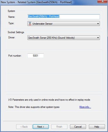
-
Multibeam
Add two multibeam systems, one for the port transducer and one for the starboard transducer.
For the port head select driver "GeoSwath Sonar (xxx KHz) Port Head".
For the starboard head select the driver "GeoSwath Sonar (xxx KHz) Starboard Head".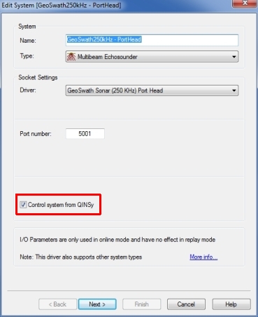
IP port number is 5001 for both heads.
To control the GS+ from Qinsy enable the option 'Control System from QinsSy'.
Online control options for the GS+ can be found in the Echosounder Settings in the Controller.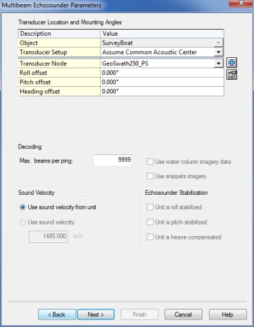
The maximum number of beams depends on the operating range of the sonar, typically leave this at 9999.
Enter around plus 60 degrees roll offset for the port head and minus 60 for the starboard head.The Node should be defined per transducer.
The center of the face of the transducer can be considered as the acoustic center and should be entered as the node offset.
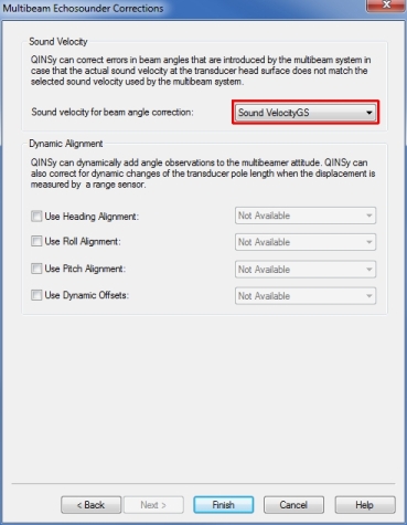
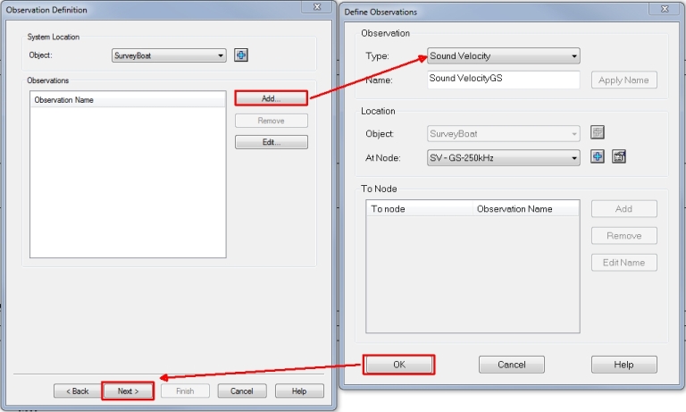
On the last page of the multibeam system wizard it is possible to enable the Sound Velocity Beam angle correction.
Select the sound velocity observation here that you defined earlier.
Do not do this if the correction is done by the Geoswath (option called 'Broadcast TXDCR Corrections' enabled).
-
Side Scan
Add a Sidescan System "GeoSwath Sonar (xxx KHz)", Select "Associated Multibeam System" to the port head multibeam system.
Add two channels:, first port, second starboard.
Select appropriate node for the channels.
All other fields are not applicable.
After you go online check that only one Geoswath.exe is found in the Task Manager.
If you find more than one please go back to Database Setup and make sure that for every system the correct driver is chosen with the same frequency (and hence command line parameter).
Qinsy Online
Online
Data Reduction
Two options for data reduction can be used: in the GeoSwath software or in Qinsy.
GeoSwath beam reduction
The sonar data from the GeoSwath is flagged after the filters/reductions are applied. To use only the data flagged as good, block on Quality outside Min/Max to 0. The GS+ data reduction does not need to be enabled.
Qinsy reduction
-
Maximum beam count
A smart beam reduction algorithm is introduced to cope with the great number of samples that are reported by this sonar system. Since every sample is translated in the driver to a beam, the CPU load caused by processing beam data from a system that pings with 15 Hz/3000 beams per swath can be too much for the pc in order to process footprints in real time. Activate the reduction. Go to "Echosounder settings" dialog, for interferometric systems the line "Max. beam count" is added to the reduction options. This works independently of the other reduction methods. Typically enable this option and select 300 here. Depending on range/sound velocity profile point count and resulting CPU load the number of kept beams may be increased/decreased. -
Median binning reduction
Input is just one figure: the bin size.
The calculated footprints are grouped in bins based on the horizontal distance between the transducer and the footprints.
The bin size is defined by the user. For every group of footprints that fall inside the bin only the median (based on Z) footprint is accepted, the others will be flagged "reduced".
By utilizing this reduction method, outliers will typically be removed, which can be useful for reducing Interferometric sonar data, characteristically these systems produce a large band of noise.Example: User sets up a bin size of 1 meter. Bins that are located at a distance between 0 and 1 meter at starboard side fall inside bin1, between 1 and 2 meters in bin2 etc. On the port side the same but then bin-1, bin-2 etc.
If within a bin multiple footprints are stored then the footprint with median Z value is selected, for example, 3 footprints: -10.2, -10,4, -10.0, the median value is -10.4 so this is the accepted beam, the others are reduced.
If the swath covers a horizontal range of 50 meters then remember that with binsize of 1 meter the reduced beam count will be only 50.Typical bin size values are 0.1 to 0.5 meters.
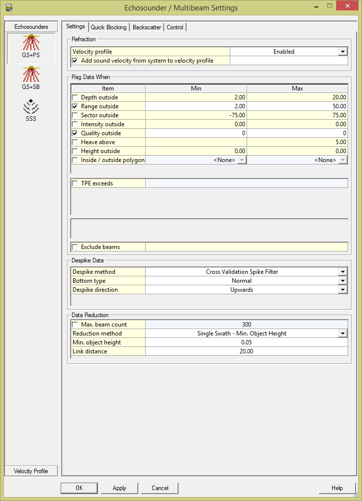
Figure: Max. Beam Count set to 300 beams, Quality blocking enabled
Tip
For more details on these Qinsy data reductions press F1 in the Echosounder Settings online.
Tip
To reduce the CPU load it is advised to use the data reduction in the GeoSwath.
Sound Velocity
The GeoSwath software calculates the beam angles from phase with a fixed Sound Velocity of 1500 m/s so therefore the beam angle corrections need always be applied. This can be done by the Geoswath or by Qinsy.
-
When this is done by Qinsy this implicates that the Mini SvS Sound Velocity Probe data should always be interfaced into Qinsy for the beam angle correction.
-
When done by the Geoswath (option called 'Broadcast TXDCR Corrections') then do not use the option in Qinsy.
This driver can also be used to control the system settings of the GeoSwath+ system in multibeam mode. This needs to be enabled in the Database Setup.
If enabled, the options are accessible in de Controller - Echosounder Settings dialog to order the GS+ system to start or stop pinging, change the range etc.
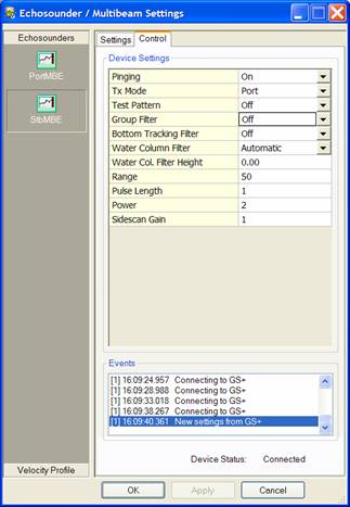
Figure: Remote Controlling the GS+ Echosounder from Qinsy
System Control
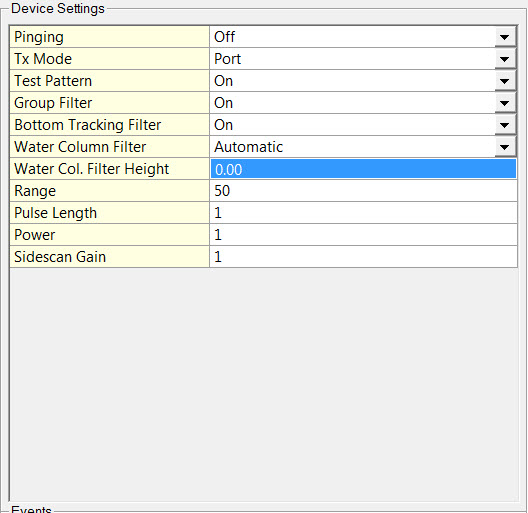
The operating settings of the sonar are modified through the Echosounder Settings dialog Control tab of the Controller.
The following settings can be modified:
|
Setting |
Description |
|---|---|
|
Pinging |
Enables and disables pinging. |
|
Tx Mode |
Select from: Off, Port, Starboard, Both. When selected this turns on the transmit pulse to the transducers. Note: For the Geoswath 4, this option has no effect as the system will keep transmitting on both heads. |
|
Test Pattern |
Switches the Test Pattern on and off. This command will set or reset the diagnostics test signal. When set on, the system will show a test pattern in the ping data indicating that the sonar system transceiver section is working.
Note that the test signal does not give any indication of possible faults with either the transmitter board or the transducers/cables.
|
|
Group Filter |
Enables and disables the Group Filter. When enabled the group filter is applied to the data prior to logging. Filtered-out points are not logged but discarded. The filter works through the range/angle samples in each ping in forward order. Samples are rejected if the sine of the angle is greater than a (learning) threshold.
|
|
Bottom Tracking Filter |
Enables and disables the Bottom Tracking Filter. When enabled the bottom tracking filter is applied to the data prior to logging. Filtered-out points are not logged but discarded. The filter works through the range/angle samples in reverse order generating a continuous mean of the sines and rejecting sines outside a threshold (approx ±17°).
|
|
Water Column Filter |
Select from Off, Manual or Automatic. Setting for water column filter, in meters below transducers. When enabled for Manual or Automatic mode the filtered points are flagged during acquisition (as ACQ_WATERCOLUMN in the rdf-file/stream) so that the filter may be undone when post-processing.
When this filter is applied during post-processing the filtered points are flagged as SWATH_LIMITS in the processed swf-file. |
|
Water Col. Filter Height |
Enter Min = 1, Max = 9999 When Water Column Filter is set to Manual, enter the height of the water column in meters below the transducers. |
|
Range |
Enter Min = 5, Max = 395 Up to 12x depth relative to the transducer positions and the vessel upon which the transducers are fixed. The range is effectively HALF the listening time after each transmit pulse.
|
|
Pulse Length |
Enter Min = 1, Max = 7 This sets the length of the transmit pulse in the water, (typically set at 1) which gives a pulse length of 16 cycles. Longer ping lengths give poorer resolution. For 125kHz system, transmit pulse length is 128µs to 896µs, i.e. 7 steps of 128µs step size.
|
|
Power |
Enter Min = 1, Max = 10 Typically set at level 1.
|
|
Sidescan Gain |
Enter Min = 1, Max = 4 This sets the gain for the Side Scan channel, (typically set at 1 or 2 for normal use). In deeper water (e.g. >50m deep) and softer bottoms this may need to be increased. |
Info
Kongsberg recommend increasing Sidescan Gain first; it doesn't improve SNR but maximizes dynamic range of the side scan signal.
Then increase Power which effectively increases SNR, although in shallow water this should be kept as low as possible.
They depend very much on the frequency of the system, the average depth, the type of water (absorption) and the type of sea bottom.
Info
Units: In the GS software the current units are displayed adjacent to the Ping Length value.
The default is meters. Clicking on the units button will globally toggle the units of GS+ to US Survey feet .
Additional Info
Drivers IO Notes
|
125: |
Use for 125Khz sonar systems |
|
500: |
Use for 500Khz sonar systems |