
Description
Driver for Geodimeter initialisation and decoding of standard output data using a Geodimeter telemetry link.
Driver to decode range observation and both horizontal and vertical angles from Geodimeter 600 system.
Driver Information
|
Driver |
Geodimeter 600
|
Interface Type |
Serial |
Driver Class Type |
|
|---|---|---|---|---|---|
|
No |
Input / Output |
Input (two-way) |
Executable |
DrvGeodimeter600.exe
|
|
|
Related Systems |
|
||||
|
Related Pages |
|
||||
System Configuration
Geodimeter Setup and Initialisation
Set up the Geodimeter instrument over a known point (fixed station node). Press the [PWR] button to switch on the instrument. Perform a calibration to determine the corrections to the observations (C-O values) and a station establishment procedure to determine the fixed coordinates of the station node, if needed. Refer for the calibration and station establishment procedures to the GEODIMETER SYSTEM 600 USER MANUAL.
Press the [RPU] button to set up the Geodimeter instrument for remote control. Press [3] to choose remote mode and [1] if no station establishment has to be performed. Set the limits of the search sector and measure towards a reference object, if needed. Press [ENT] or another button to switch over to the remote control.
Geodimeter Radio Channel and Address
The radio channel, telemetry radio address and Geodimeter radio address are read from file GEORADIO.txt which is located in the Qinsy program directory. This file is created the first time the Geodimeter driver is started. It's contents can be changed (before going or while being) online, after which a "Reset I/O" can be given to re-initialise the telemetry link. Only change the numbers; do NOT change the comment strings.
1 GEORADIO CHANNEL
1 GEORADIO ADDRESS
1 GEODI600 ADDRESS
Interfacing Notes
Geodimeter interface parameters can be set using the keyboard, and are default 9600 baud, 8 data bits, 1 stop bit, no parity.
The latency of the Geodimeter system is the interval between the time of receiving the first byte of the standard output data transmission and the time at which the actual measurements have been made.
The Geodimeter telemetry output is an ordinary RS232 output.
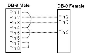
For some Trimble tracking total stations such as the S8 it can be necessary to use a cable according to this wire diagram.
Database Setup
Add an "Object" for the vessel with the target unit. Add a "Fixed Node" for the Geodimeter station. Add a "Variable Node" (on the vessel object) for the target unit to be used for online positioning. Be sure to enter right offsets. A physical horizontal offset, in case of a ring of prisms, should be entered as a correction to the range, see below. Add a "Surface Navigation System" with driver "Geodimeter 600 (Active Radio Link)" (Active RS232 Link has not been implemented yet) and enter the appropriate interfacing parameters and latency value. In the system definition wizard select the location(usually fixed), add observations for Range horizontal angle and vertical angle, for each observation select the from and to node.
Enter the appropriate slot number, which is the label number in the standard output data transmission, i.e.
"9" for range, "7" for horizontal angle, and "8" for vertical angle. See appendix to the USER MANUAL.
On the last page of the wizard: Observation unit for the range should be "meters". Calibration corrections (and prism offset) for the range can be entered under Properties. Observation units for the angles should be "grads". Calibration corrections can be entered under Properties. The calibration (C-O) values can be entered in the "Fixed (C-O)" or "Variable (C-O)" properties of the three observations.
Important 1)
Since the horizontal angle is defined as "true bearing" observation, its (C-O) value must reflect the difference between the zero direction in the Geodimeter instrument and true north. The (C-O) correction is added to the observed value before it is used by Qinsy. Since the vertical angle is really a zenith angle, measured downwards from the zenith instead of upwards from the horizon, its scale value (C/O) must be -1 (minus 1). The (C-O) value for the vertical angle must be -100 (minus 100), 100 grads to account for the zenith direction and minus to account for the fact that the general observation reduction equation in the Qinsy system (following UKOOA P2/94 format) is defined as Obs reduced = (C/O) { Obs raw + (C-O) fixed + (C-O) variable }.
Important 2)
The Geodimeter can not send the first trigger to the computation. A position simulator must be added to the Database setup which must be selected as triggering system to give the computation the first trigger.
When the computation starts working, the simulator must be switched off in the computation setup.
Drivers IO Notes
Command line parameter description for "drivers.io" file in Qinsy directory. By default, the Geodimeter 600 driver is initialized in actively radio controlled tracking mode, with a 10 seconds timeout for a lock failure.
|
Parameter |
Description |
Default |
Comments |
|
C |
RS-232 control |
off |
direct cable connection |
|
R |
radio control |
off |
radio link ; same as 'A' |
|
A |
active control |
on or off |
radio link ; see DRIVERS.IO entry |
|
P |
passive control |
off or on |
radio link ; see DRIVERS.IO entry |
|
L |
tracking mode |
on or off |
radio link ; see DRIVERS.IO entry |
|
F |
standard mode |
off |
measuring mode |
|
N |
passive mode |
off or on |
measuring mode ; same as 'P' |
|
TRK |
tracking mode |
on or off |
measuring mode ; same as 'L' |
|
STD |
standard mode |
off |
measuring mode ; same as 'F' |
|
NTC |
no target check |
on |
disables "RG,32" target status command |
|
BOX |
message boxes on |
off |
displays radio link status message boxes |
|
Nn |
lock failure count |
20 |
< 100 ; counter before re-initialization |
|
nnn |
command delay in ms |
750 |
> 100 ; milliseconds to delay commands |
Parameter "C" can be used for a RS-232 link; parameters "R" and "A" indicate an active radio link while "P" and "N" initialize a passive radio link (not sending commands). Parameters "L" or "TRK" can be used for tracking mode, while "F" or "STD" are used for standard mode. An integer number (less than 100) can be used to set the count of consecutive lock failure status responses (i.e. the "RG,32" responses), before a message (and target search command) is given. An integer number (greater than 100) can be used to set the time interval (milliseconds) between sending a command (i.e. the "RG" request) and reading a response.
If the update rate of the Geodimeter system is set to more than one second, the integer number will represent the number of seconds. See below for the driver entries that a presently available in the "drivers.io" file.
Remark
In case of an active radio link, using a command delay of 750 ms and with the target check enabled, will mean that only one set of measurements every 1.5 seconds will be read. Using "NTC" as command line parameter will decrease the measurement interval to 0.75 seconds, but then the driver will not be able to determine of the target lock is lost. In (default) tracking mode, 0.4 seconds is needed to measure a distance, plus some time to send the data over the radio link, so do not use command delays less than 500 ms.
Remark
When a passive RS-232 cable link is being used, it is better to use the Qinsy DrvGeodimeterGST module.
100077, Geodimeter GST (Passive RS232 Link) , DrvGeodimeterGST.exe
100078, Geodimeter 600 (Passive Radio Link) , DrvGeodimeter600.exe P 20
100079, Geodimeter 600 (Active Radio Link) , DrvGeodimeter600.exe A L 20 750