
Description
-
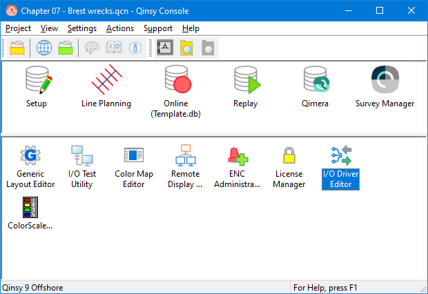
The I/O Driver Editor is started from the bottom pane of the Console:
-
It can be used for:
-
Creation of a user-defined input driver
-
Creation and/or editing of generic drivers for an OPC Server
-
Decoding of multiple systems from a server
-
Decoding of multiple strings for a single server
-
For each string that needs decoding, a separate driver needs to be created
-
-
-
The OPC driver needs to be added to your Qinsy license as a separate add-on utility
Driver Information
|
Driver |
Generic OPCUA Input |
Interface Type |
OPC UA |
Driver Class Type |
Terminated |
|---|---|---|---|---|---|
|
No |
Input / Output |
Input |
Executable |
DrvInputOpcUAClient.exe |
|
|
Related Systems |
|
||||
|
Related Pages |
|
||||
Database Setup
-
After creating a driver, it can be used in the template database to decode data strings.
If multiple strings need to be decoded for a single server:-
Select for each system you want to decode the created driver
-
Select the same endpoint URL
-
-
Is the server protected by username and password?
-
Add those to the server url
-
<endpointUrl>;<username>;<password>
-
Use ';' (semicolon) as separation character for the credentials
-
-
Acceleration Velocity Sensor
-
Not to be used yet.
-
-
Dredging Sensor
-
Driver reports active if value not equal to 0.
-
Please note that the driver does not use the C-O and multiplication factor from the GUI in Database Setup.
-
Online
QPS defined driver definition files (installed with Qinsy) are stored under the Qinsy installation folder in the following location: <Qinsy install folder>\Drivers\Definitions\Input
User defined / edited driver definition files are stored in the Windows Common Documents folder: <common documents>\QPS\QINSy\Drivers\Definitions\Input (Normally, Common Documents is located at C:\Users\Public\Documents)
The configuration file for a generic serial input driver is conform the following layout:
Layout
[General]
Revision=File format revision
Version=Ini file version
Description=Driver name as displayed in DbSetup
Name=Driver name without spaces (used internally)
Type=System types under which driver will be displayed in DbSetup         (Table 1)
Executable=Driver executable name that should be used
Slots=Slotcount defined per system
[String]
StartChars=Fixed string that should be present at start of each update
TerminationChar=decimal ASCII character that terminates each update       (Table 2)
SeparationChar=decimal ASCII character that separates each field          (Table 2)
MinimumLengthFlag=Minimum length check enabled flag
MaximumLengthFlag=Maximum length check enabled flag
MinimumLength=Minimum length of each update
MaximumLength=Maximum length of each update
NumberOfItems=Number of fields decode from the string
[Checksum]
Enable=Checksum computation enabled flag
Method=Methode used to compute checksum                                   (Table 3)
StartAt=Location to start checksum computation
StopAt=Location to stop checksum computation
Position=Location of checksum in the update
Length=Length of checksum information
Encoding=Encoding method of checksum                                      (Table 4)
[Time tag]
ApplyGPS2UTC=Correct time for GPS-UTC time offset
UseSystemDate=Use system date for time tag
[Item 1]
SystemId=System tye
Record=IPC record                                                         (Table 1)
Field=IPC field                                                           (Table 5)
Encoding=Encoding method used                                             (Table 6)
Mask=Mask used during encoding                                            (Table 7)
Position=Position of item in update
Length=Length of item in update
Factor=Multiplication factor
MinimumValueFlag=Minimum length check enabled flag
MaximumValueFlag=Maximum length check enabled flag
MinimumValue=Minimum length of each update
MaximumValue=Maximum length of each update
Slotnumber=Automaticaly generated
Obsname=User defined observation name
For more information see the F1 inline help of the I/O Driver Editor utility.
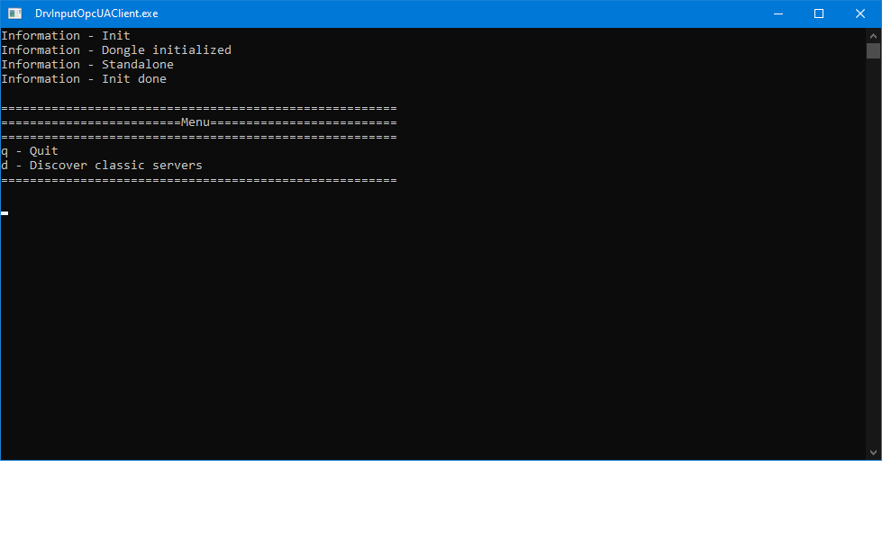
This driver also supports connection to a classic OPC server (DCOM ).
To get the correct connection URL you can start the driver stand alone.
-
A command line will appear.
-
Enter the discover option and the available DCOM servers will be printed.
-
Use the printed endpoints as endpoint in Database Setup.
An alternative would be to start the driver from a command line:
-
Windows key + R
-
Enter cmd.exe
-
Navigate to the Qinsy install directory
-
cd C:\Program Files (x86)\QPS\QINSy\<version>
-
-
Execute command:
-
DrvInputOpcUAClient.exe -d
-
Some manual steps might be necessary when connecting to a server that does not automatically trust an OPC client.
Some OPC servers automatically trust any client. Other OPC servers might inform the user about a "rejected" client wanting to connect. And some need a manual action.
Most, if not all, OPC servers have a certificate store that validates any client trying to connect. The locations of these certificates are dependent on the server implementation.
The default location to look for is : C:\ProgramData\<vendor/manufacturer>\
For Qinsy the store is located at : C:\Users\<user>\AppData\Local\QPS\OpcClient and C:\Users\<user>\AppData\Local\QPS\OpcServer
If the QPS OPC Client is unable to connect to a server due to it being rejected, please find the location of the OPC server certificate store on the host machine.
The server should have created a certificate for any rejected client and placed it in the <storelocation>\rejected folder. Moving the certificate to the "Trusted" folder should fix the connection problem.
Additional Information
Additional info for Magnetometers
Database Setup
Add manual echosounder
Please be aware that you need to add a Manual echosounder to your towed object to be able to process the track of the towed object.
Online / Replay
Since Qinsy version 8.10.2014.10.20:
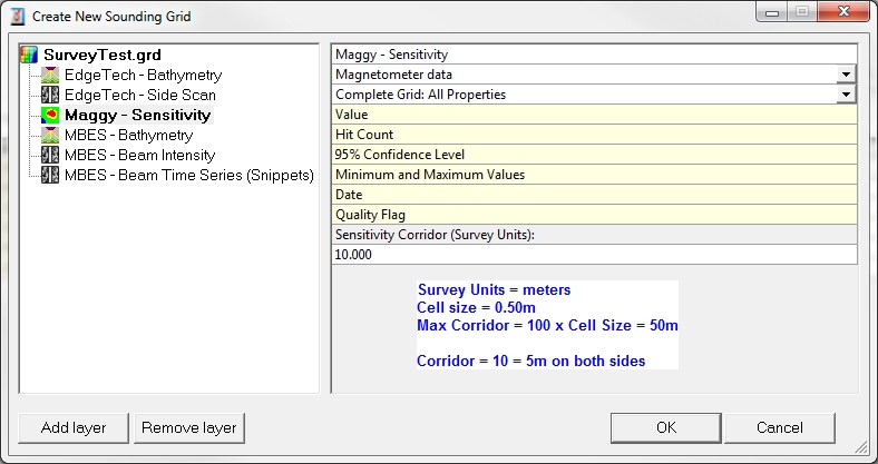
Storing magnetometer data to a sounding grid has the option to create a corridor perpendicular to the sailing direction. I.e. that the full path of the corridor is filled automatically with each single reading of the magnetometer.
To set this corridor width value, go to the Layer properties in the Controller's Session Setup, Storage, Sounding grid or use the Sounding Grid Utility, making sure that the layer type is 'Magnetometer data'.
The maximum width of the corridor is 100 times the minimum cell size of the sounding grid.
Driver History
-
Since 8.10.2013.01.24.1
Generic Driver Multiple String Support
The Generic Driver was modified so that multiple definitions (ini-files) may be attached to a single serial port.
This makes it possible to decode multiple systems of the same type from a single telegram.
In order to do this a definition should be made for each system.
-
Since 8.10.2013.05.06.1
Generic Driver Network UDP Supports
Use the Console to start the I/O Driver Editor, select driver type 'Generic Input' and state on the General Information Wizard page whether the IO should be serial or from UDP.
Note that IO COMport settings or the UDP port number must be selected in Dabase Setup when adding a system using this generic driver.