
Description
Driver to decode data in real-time from a FarSounder 3D Forward Looking Sonar.
The FarSounder Argos series comes with three products: Argos 350, Argos 500 and Argos 1000.
The main difference between those is the maximum range of detection. All three products are supported by this driver.

Argos 350 Transducer Module |

Argos 500 Transducer module |
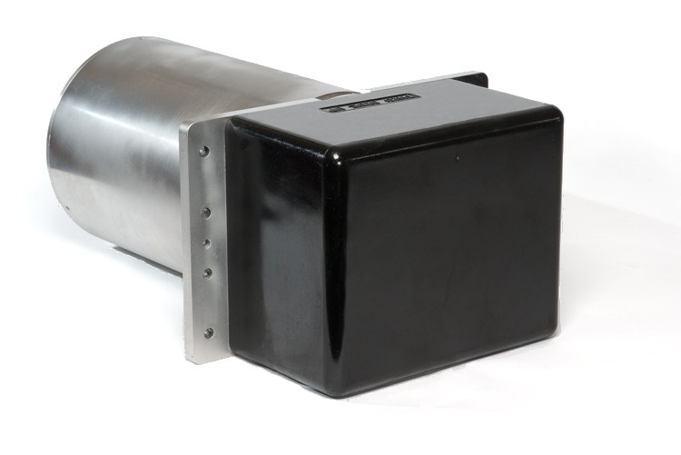
Argos 1000 Transducer module |
Driver Information
|
Driver |
FarSounder (Forward Looking Sonar) |
Interface Type |
TCP |
Driver Class Type |
Freebase |
Created |
|
|---|---|---|---|---|---|---|---|
|
Yes |
Input / Output |
Input/Output |
Executable |
DrvFLSControl FARSOUNDER |
Updated |
|
|
|
Related Systems |
|
||||||
The following data that is published by the FarSounder can be decoded by this driver:
-
Seabed data from the bottom detection
-
Decoded as multibeam xyz observations and therefore stored as footprints in your DTM point cloud file or sounding grid.
For this data you need to setup a Multibeam Echosounder system.
-
-
In-water detected objects
-
Decoded as multibeam xyz observations and therefore stored as footprints in your DTM point cloud file or sounding grid.
For this data you also need to setup a Multibeam Echosounder system. -
Optionally decoded as ARPA target observations and therefore easily visualized in a Navigation Display.
For this data you need to setup an ARPA system.
-
-
The GPS latitude and longitude and gyro heading used by the FarSounder
-
For reference this may be useful to decode as a separate Position Navigation and Gyro system.
-
The FarSounder unit comes with their own software called SonaSoft:
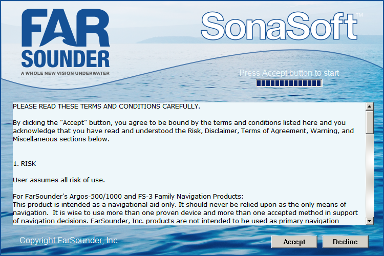
SonaSoft is needed to communicate directly to the hardware and is responsible for processing, encoding and publishing all target detected data.
SonaSoft should always run for Qinsy to receive data.
This document does not describe how to operate the SonaSoft software but here you will find some tips of the most important settings you can expect.
At time of writing SonaSoft version 3.11 was used.
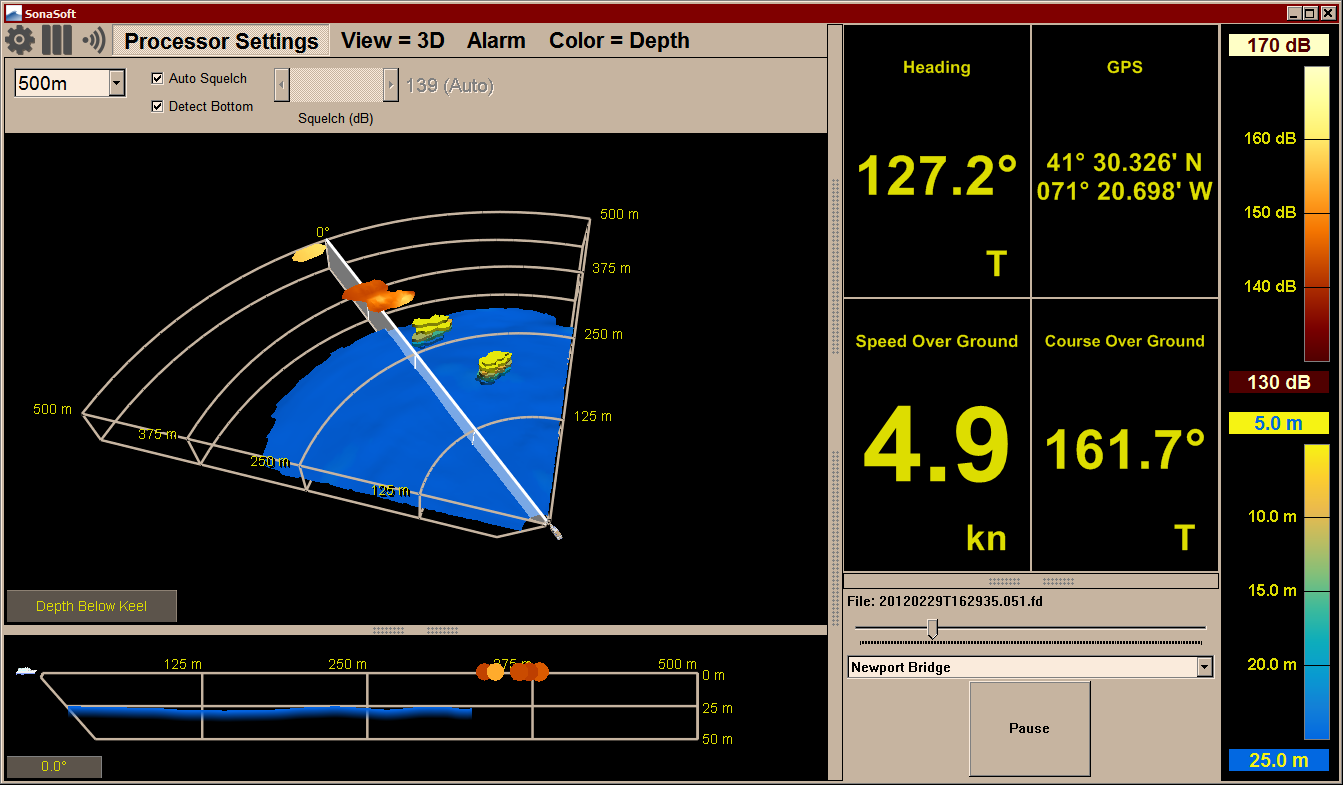
Three settings can be found in the Processor Settings menu:
-
Field of View
Use the Field of View drop down selection to change the current range/sector width mode.
Changing the field of view has immediate effect on the data being published to Qinsy. -
Auto Squelch
Enable this setting is recommended for detection of in-water: in that case SonaSoft will automatically determine the best detection threshold using adaptive threshold methods.
When not enabled, a manual value (using the slider) will be used.
In general a squelch value is used for detecting in-water targets:
- When the squelch level is low then targets with smaller reflectivities can be detected, however noise may be increased.
- When the squelch level is high then more noise is filtered out from the detection algorithm, however this is done at the cost of smaller target detection.
For detailed information about squelch and how to use this setting please consult the operators manual.
-
Detect Bottom
Enabling this setting will force the algorithm to detect the seabed under the condition that the vessel operates in water not deeper than 50 meters (165 feet).
This means that Qinsy will receive seabed data from bottom detection next to possible in-water detected objects.
When this setting is disabled then Qinsy will only receive possible in-water detected objects and no seabed data.
Therefore changing this setting has immediate effect on the data being published to Qinsy.
If this setting is enabled when the actual sea floor is deeper than 50 meters it may incorrectly publish a 'crazy' sea floor at a clearly incorrect location.
Therefore it is recommended to disable bottom detection when the vessel is operating in water depths deeper than 50 meters, so in that case the algorithm will not try to find the sea floor and will avoid any 'crazy' bottoms.
On the other hand if this setting is not enabled while the vessel is operating in waters shallower than 50 meters deep, echoes reflecting from the bottom may appear as a series of in-water targets at or near the expected bottom depth which is also unwanted.
In this case it is recommend to enable bottom detection.
For detailed information about bottom detection and how to use it please consult the operators manual.
With Qinsy v9.2 you can monitor those settings under the Controller Online Settings and it is also possible to change them immediately from within Qinsy (except for the Field of View setting).
As mentioned before, the FarSounder unit comes with FarSounder's own software called SonaSoft which is needed to communicate directly to the hardware.
The Qinsy driver uses a TCP network connection in order to communicate with SonaSoft.
Use a fast (Gigabit) network card, due to the enormous amount of data to be expected.
By default FarSounder configures their products with the following subnet range: 192.168.0.x, where x is 2, 3, 4, 5 or 254.
So make sure that the Qinsy network is in the same range except for the last digit: this must be different.
For example:
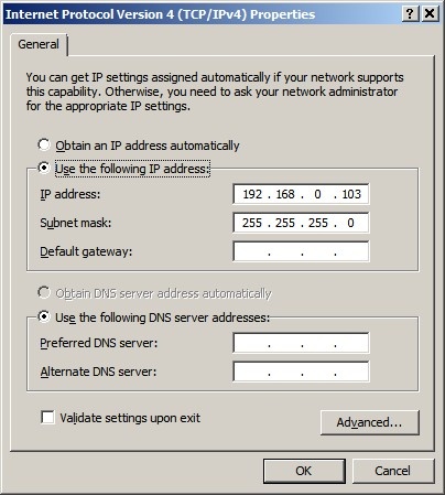
Set the subnet mask to 255.255.255.0.
It is advisable to check the network connection between your computer and the unit prior to going online.
You may do this by using the ping command from the Windows Command Prompt:
Select Start from the Windows Task bar, Run..., Cmd <Enter>, and 'ping' the address of the FarSounder unit.
For example: suppose the FarSounder IP address is 192.168.0.1.
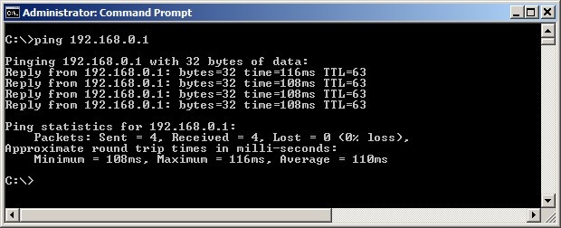
The network connection is okay when you receive a reply three times within a few milliseconds.
If you can't ping the sonar's address successfully, it is no use continuing: first a valid network connection must be established between scanner and Qinsy computer.
Shared Computer Setup
Qinsy and SonaSoft can run simultaneously on the same computer but such installation is not recommended: both programs use a lot of system resources so each program will affect the performance of the other one.
Another unwanted effect is that SonaSoft will modify the current Windows Theme while running and this will also affect the look and feel of Qinsy.
If you do need to run both programs on the same computer (e.g. for test purposes) then use IP address 127.0.0.1 in your Qinsy Config databasesetup.
Normally a Qinsy driver will time-stamp the data when received at the network port using the computer's own internal clock. Due to network characteristics in general this will result in inaccurate timing, e.g. because of network latencies.
Best scenario is that all systems should work in the same time frame. In practice this means that both Qinsy and the FarSounder should use an accurate Time Synchronization system (a.k.a. PPS) using the same time source.
In that case the Qinsy driver will use the decoded time stamp which is available in the published target data.
It does depends on the following criteria:
-
Qinsy must be interfaced to a valid Time Synchronization system.
-
Online setting Timing must be set to 'use FarSounder time'.
In case you don't trust the time of the FarSounder (e.g. not using the same time frame as Qinsy) then Online setting Timing must be set to 'use Qinsy time'.
Always check the timing status and more important the age of the decoded data with a Generic Display.
The following data that is published by the FarSounder can be decoded by this driver:
-
Seabed data from the bottom detection
-
Decoded as multibeam xyz observations and therefore stored as footprints in your DTM point cloud file or sounding grid.
-
-
In-water detected objects
-
Decoded as multibeam xyz observations and therefore stored as footprints in your DTM point cloud file or sounding grid.
-
Optionally decoded as ARPA target observations and therefore easily visualized in a Navigation Display.
-
-
The GPS latitude and longitude and gyro heading used by the FarSounder
-
For reference this may be useful to decode as a separate Position Navigation and Gyro system.
-
Database Setup
Seabed data from bottom detection
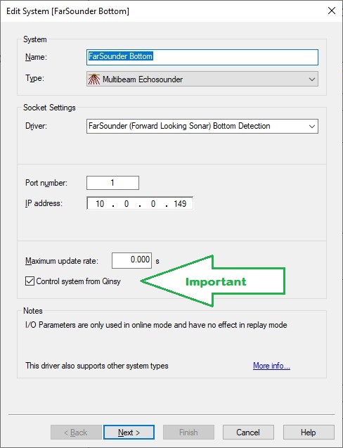
Add a Multibeam Echosounder system to your template setup and select driver "FarSounder (Forward Looking Sonar) Bottom Detection".
Edit System
-
The Port number is not used and can be ignored, so leave the port number to 0.
(Note that in the above example 1 is used so in that case you must use 1 for all other systems) -
The IP address must be the IP address of the computer running the SonaSoft software.
-
Leave the Maximum update rate at zero.
-
Important: Enable the setting Control system from Qinsy.
When enabled you will get an extra Control page in the Echosounder Settings of the Controller while working online in order to communicate with the unit.
Multibeam Echosounder Parameters
Important are the location of the Transducer Node and the Mounting Angles (Roll/Pitch/Heading offsets) on the second wizard page.

-
The exact values for the roll, pitch and heading offsets should be established with a patch test/calibration procedure.
-
Leave the Max. beams per ping value at 9999.
The actual number of beams will be variable and depends for example on the used online settings and on the targets being scanned. -
Important: Make sure to enable all three Echosounder Stabilization settings.
It means that Qinsy expects that all received data is already corrected for motion by the FarSounder unit.
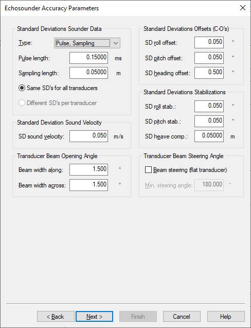
Echosounder Accuracy Parameters
This last wizard page can be skipped, so leave all values at their defaults.
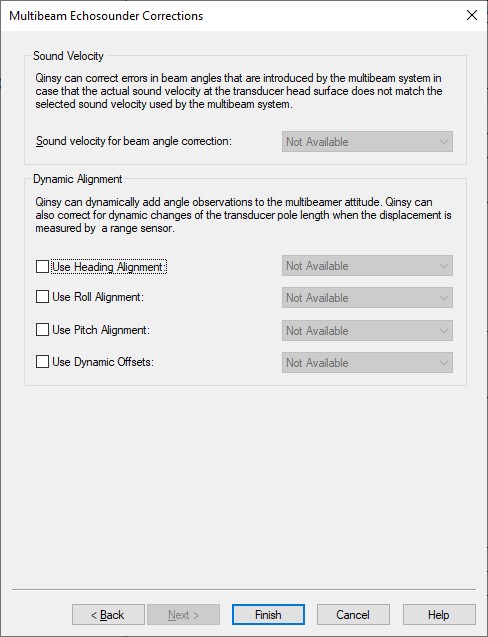
Multibeam Echosounder Corrections
This last wizard page can be skipped, so leave all values at their defaults.
In-water detected objects
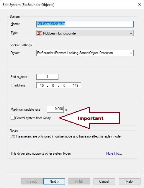
Add another Multibeam Echosounder system to your template setup and select driver "FarSounder (Forward Looking Sonar) Object Detection".
Edit System
-
The Port number is not used but must be the same as entered for the other defined Multibeam system
-
The IP address must be the IP address of the FarSounder computer and the same as entered for all the other systems
-
Leave the Maximum update rate at zero
-
Important: Leave the setting Control system from Qinsy unchecked.
The setting should already being enabled by the other defined Multibeam system and you should only have one Control page in the Controller while working online.
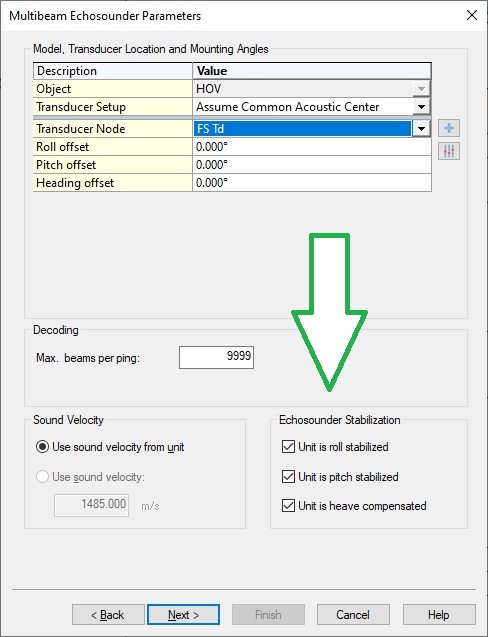
Multibeam Echosounder Parameters
Important are the location of the Transducer Node and the Mounting Angles (Roll/Pitch/Heading offsets) on the second wizard page.
-
The exact values for the roll, pitch and heading offsets should be established with a patch test/calibration procedure.
-
Leave the Max. beams per ping value at 9999.
The actual number of in-water detected objects will be variable and depends for example on the used online settings and on the targets being scanned. -
Important: Make sure to enable all three Echosounder Stabilization settings.
It means that Qinsy expects that all received data is already corrected for motion by the FarSounder unit.
Echosounder Accuracy Parameters
This last wizard page can be skipped, so leave all values at their defaults.
Multibeam Echosounder Corrections
This last wizard page can be skipped, so leave all values at their defaults.
In-water detected objects
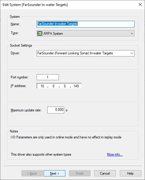
Add an ARPA System to your template setup and select driver "FarSounder (Forward Looking Sonar) In-water Targets".
Edit System
-
The Port number is not used but must be the same as entered for the other defined Multibeam system
-
The IP address must be the IP address of the FarSounder computer and the same as entered for all the other systems
-
Leave the Maximum update rate at zero
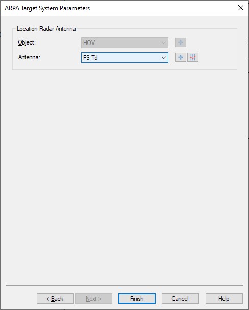
ARPA Target System Parameters
-
Select the vessel and the node that represents the location of the FarSounder Transducer module and Finish the setup.
FarSounder gyro heading
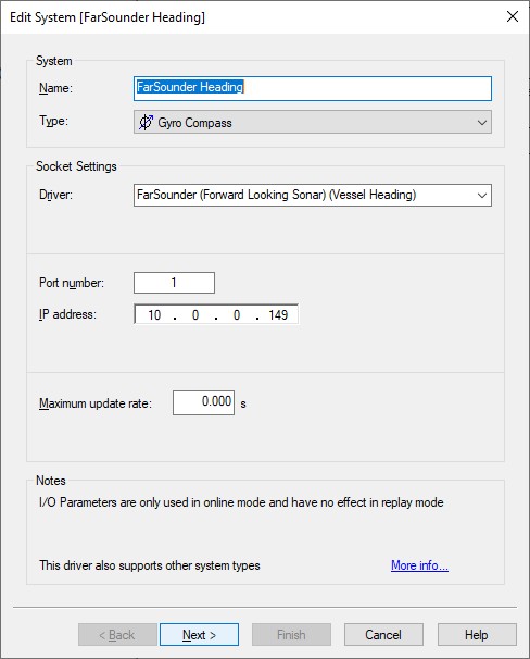
Add a Gyro Compass to your template setup and select driver "FarSounder (Forward Looking Sonar) (Vessel Heading)".
Note that the decoded heading is coming from the gyro that is interfaced (via NMEA sentences) into the FarSounder unit.
The update rate can be slow, intermittent or delayed.
Therefore you should only use this decoded heading as reference and not for survey.
Edit System
-
The Port number is not used but must be the same as entered for the other defined Multibeam system
-
The IP address must be the IP address of the FarSounder computer and the same as entered for all the other systems
-
Leave the Maximum update rate at zero
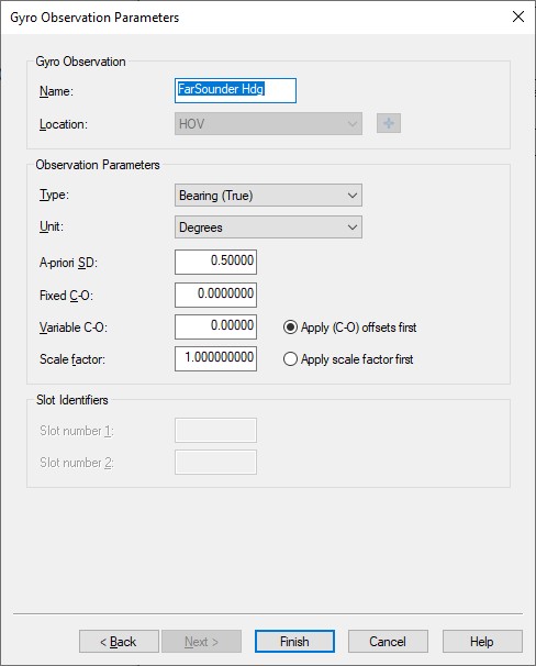
Gyro Observation Parameters
-
Leave all parameters at their defaults
FarSounder GPS latitude and longitude
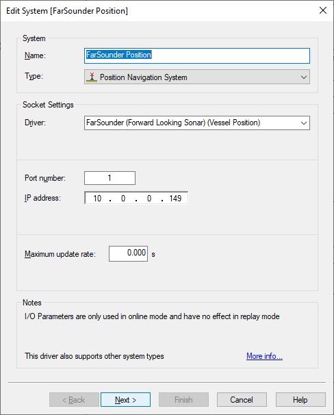
Add a Position Navigation System to your template setup and select driver "FarSounder (Forward Looking Sonar) (Vessel Position)".
Note that only a latitude and longitude observation is decoded (most likely on the WGS84 datum) and no height observation.
It depends on the GNSS that is interfaced (via NMEA sentences) into the FarSounder unit.
The update rate can be slow, intermittent or delayed.
Therefore you should only use this decoded position as reference and not for survey.
Edit System
-
The Port number is not used but must be the same as entered for the other defined Multibeam system
-
The IP address must be the IP address of the FarSounder computer and the same as entered for all the other systems
-
Leave the Maximum update rate at zero
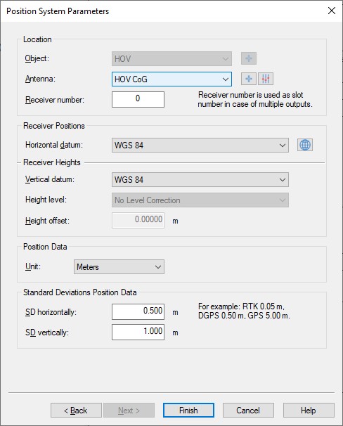
Position System Parameters
-
Select the correct antenna location that represents the position.
-
Leave the other parameters at their defaults.
Online
Most control of the FarSounder is done using the sonasoft program running on the dedicated FarSounder computer.
Little additional control is needed for Qinsy: once you go on-line a connection will be made automatically and the driver starts decoding any incoming messages.
However, there may be circumstances that you need to make a manual connection with the FarSounder computer, or that you want to limit the maximum forward looking range, or others.
In that case select Echosounder Settings, click on the System icon, and select the 'Control' tab page.
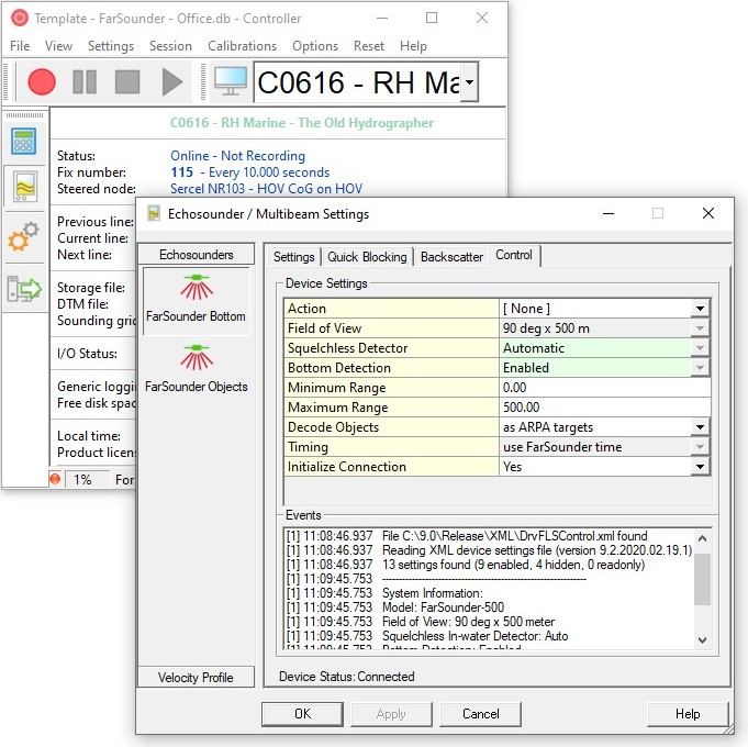
Note when two sonar system are defined in your setup (one for bottom and one for in-water target detection) you'll get two icons but only one system should have a 'Control' tab with device settings.
So changing any setting will affect both systems.
|
Control |
Device Setting |
||
|---|---|---|---|
|
Action |
Selected action will be sent to the sonar unit, immediately after hitting the Apply or OK button. You must have initialized the connection first in order to select any action. Note that any selection will always revert back to [ None ], after each selected action. Always wait a few moments after each action, until the status in the Event list is updated with a message. It takes some time before the unit handles the requested command (action) and reverts back.
|
||
|
Field of View |
Here you'll see the current selected range/section width mode (Field of View) from the SonaSoft Processor Settings. Possible values could be:
but all depends on the FarSounder model being used (Argos 500 / Argos 1000) and the selection made in the SonaSoft Processor Settings. Note that this field is read-only; it only shows what has been selected in SonaSoft. It is the intention that future versions of this driver allow you to change this setting immediately. |
||
|
Squelchless Detector |
Here you'll see the current selected Auto Squelch setting from the SonaSoft Processor Settings.
When you change this setting here it will update the setting in SonaSoft and vice versa. More information about squelch can be found in the systeminterfacing pane under section SonaSoft. |
||
|
Bottom Detection |
Here you'll see the current selected Detect Bottom setting from the SonaSoft Processor Settings.
When you change this setting here it will update the setting in SonaSoft and vice versa. More information about bottom detection can be found in the systeminterfacing pane under section SonaSoft. |
||
|
Minimum Range |
Set the minimum required range (horizontal forward looking distance) in meters. Valid values between 0 and 500 meters. Note that blocked data (any in-water targets or bottom data detected closer by than this threshold) will not be recorded! |
||
|
Maximum Range |
Set the maximum allowed range (horizontal forward looking distance) in meters. Valid values between 0 and 500 meters. Note that blocked data (any in-water targets or bottom data detected further away than this threshold) will not be recorded! |
||
|
Decode Objects |
This setting is only visible when your setup has an ARPA System defined (see databasesetup) in order to decode the in-water detected objects as Target observations.
|
||
|
Timing |
Important is to check the Status Flag in a Generic Display: a value of 2 means that both conditions were met. More information about Timing can be found in the systeminterfacing pane. In order to change the Timing you need to be disconnected. |
||
|
User Defined |
This advanced setting may not be visible. Here you may overrule the default subscriber and request port numbers. Please contact QPS for assistance and guidance in case you need to change the default port numbers. In order to change these values you need to be disconnected. |
||
|
Initialize Connection |
A TCP connection needs to be established between Qinsy and FarSounder using the given IP address from the template setup. Note that the driver will automatically connect at startup and disconnect when going offline. In a situation where you experience problems you may disconnect temporarily and then connect again.
More information about Network can be found in the systeminterfacing pane. |
Alert Display
An Alert Display is useful to see if data is coming in regularly at the I/O port.
Therefore it should be the first display to check when going online.
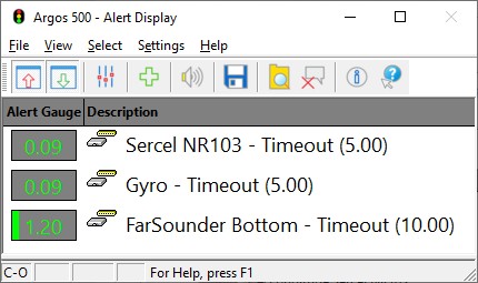
Although you may have defined 5 different systems in your setup to decode data from the FarSounder it is sufficient to select only one of them here, because they all use the same time stamp.
Observation Physics Display
An Observation Physics Display is not useful for monitoring if or how multibeam data is decoded, but can be useful to monitor the individual decoded in-water target objects from the ARPA system.
For each decoded target you will see the range and bearing and the x, y, z offset.
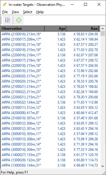
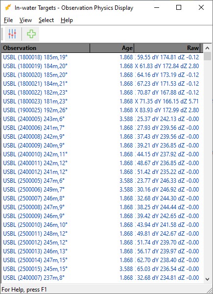
Note that in-water detected objects decoded as ARPA target observations will only have an X-offset and Y-offset property, but no depth information.
USBL target observations will have an extra Z offset property that contains the depth information.
Generic Display
Use a Generic Display to show additional values decoded from each ping header:
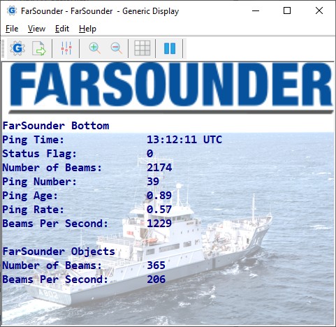
The status value is a number and can be 0 (zero) or 2: a value of 2 means that the time of the FarSounder is being used and 0 means that the Qinsy computer time is used for time stamping.
In both scenarios the Ping Age value (sec) should be around zero. When the FarSounder time is being used but you do see a large ping age it means that both computer times are out of sync.
More information about Timing can be found in the systeminterfacing pane.
Raw Multibeam Display
Use this display to visualize the raw incoming multibeam data.
Normally the displayed data will be uncorrected for motion but unlike other multibeam systems the FarSounder delivers already corrected data.
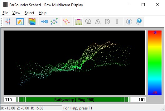
The display will give you a good indication of a) whether data is coming in b) what the approximately swath width is and c) the approximate depth below transducer.
Use the Auto Scale button to show all data from the last ping inside the view. Bear in mind that all forward detected data is presented in a 2D way.
Swath System Display
Use this display to visualize the calculated DTM results.
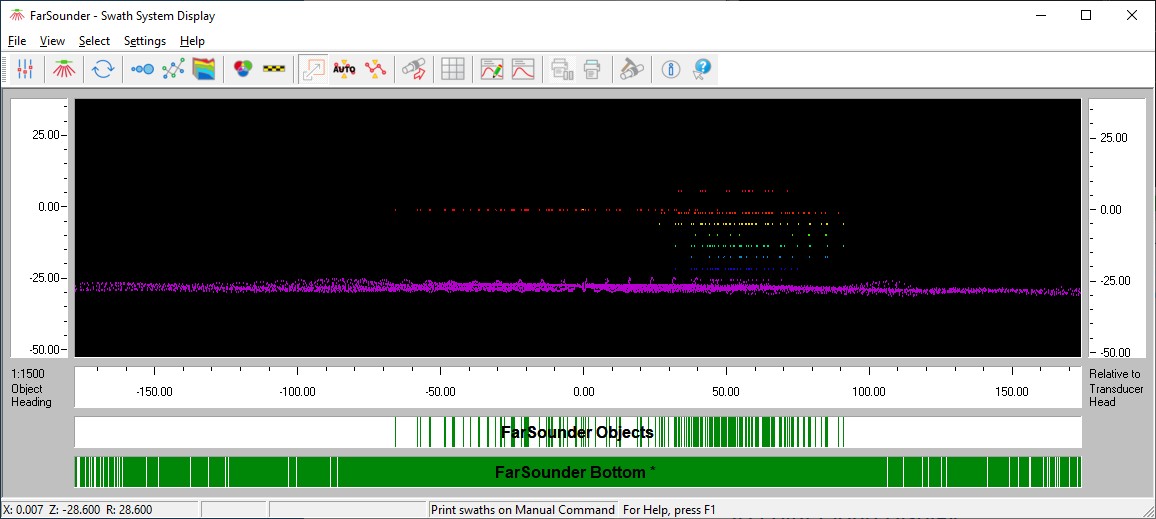
Here you can show data from both multibeam systems simultaneously.
It is recommended to enable the Scaled Display setting to have a preserved aspect ratio of the vertical and horizontal axe.
Bear in mind that like the Raw Multibeam Display all forward detected data is presented in a 2D way.
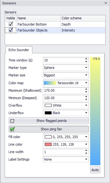
3D Point Cloud Display
Use this display to visualize the calculated DTM results in a 3D environment.
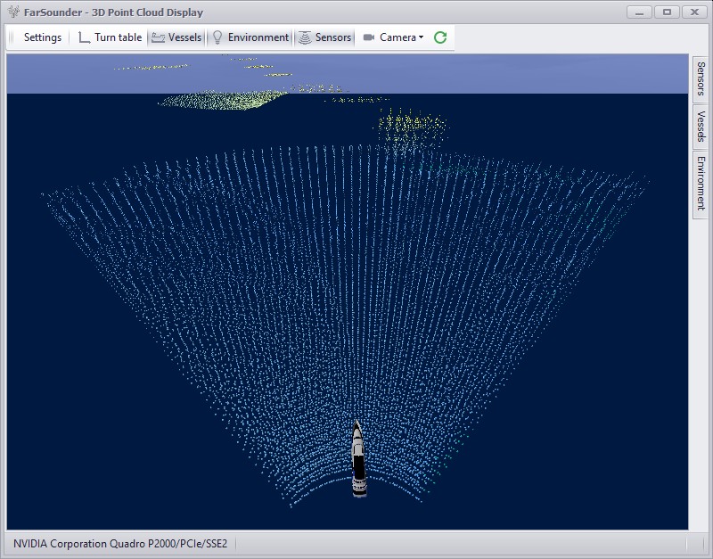
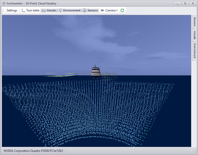
Use the Sensor settings to quickly enable or disable viewing data from one or both multibeam systems and each system will have its own color scheme and properties.
It is recommend to use a small Time window (e.g. 10 seconds). Also use the Sensor settings to show or hide the ping fan.
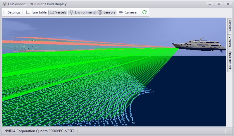
Use a Navigation Display to view the updating Sounding grid or Dynamic Surface during recording.
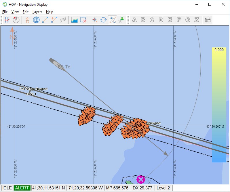
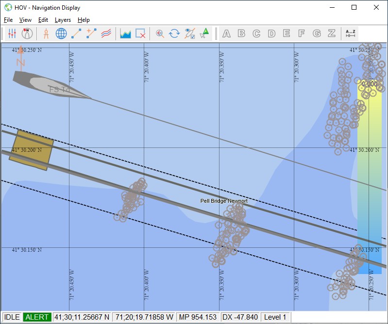
In order to visualize the in-water detected objects decoded as ARPA/USBL targets you will need to enable the 'Other system targets' setting which can be found under View Properties, Layers, Targets:
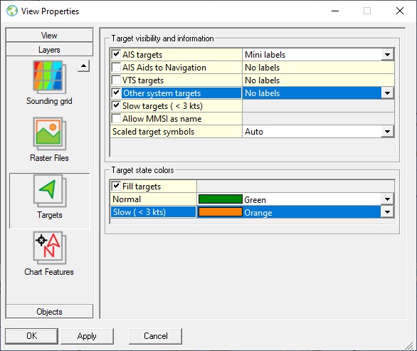
ARPA decoded targets are always presented as triangles (pointing towards the vessel) for which you may change the color. For this use the Slow (< 3kts) color setting (target speed is always zero).
USBL decoded targets are always presented as gray circles for which you can't change the color.
No Data
Problem
Qinsy does not receive any data from the FarSounder, although the SonaSoft is up and running and the connection is okay.
Further, when you use action 'Request System Information' then no response is received.
Possible explanation
Open the Windows Taskmanager on the FarSounder computer and go to the Services tab-page.
Here you should notice several 'farsounder_' services running in the background:
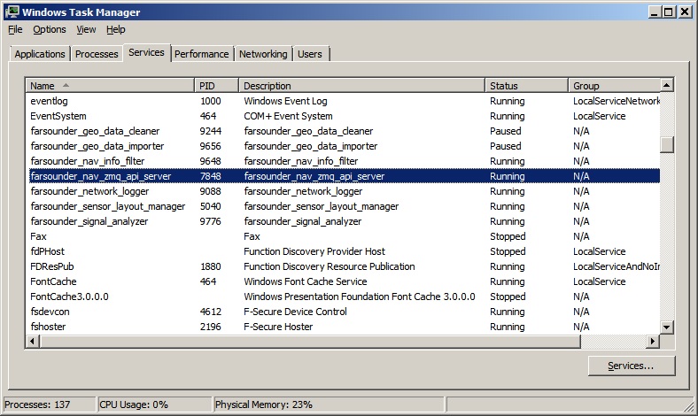
Important is that the status of service farsounder_nav_zmq_api_server indicates 'Running'.
When the status indicates 'Stopped' or 'Paused' then Qinsy will not receive any data.
Solution
Reboot the system and restart SonaSoft.
Contact manufacturer FarSounder if that doesn't help.
In the SonaSoft program installation folder you may find a subfolder logs containing a log file. Please submit this log file to FarSounder so they can investigate the problem.
Network
Daily Log File
All user actions, requested system information and reported errors are logged in a daily log file which can be found in the current project's LogFiles subfolder.
The filename convention for this ASCII log-file is <System Name> DD-MM-YYYY.log, so every day there will be a new one.
Note that all time stamps in this log file are by default in UTC. An advanced user may change this to local time zone (LTZ) by changing the following registry key:
HKEY_CURRENT_USER\Software\QPS\QINSy\8.0\Drivers\DrvFLSControl\Settings\TimeLogFileUtc value from 1 to 0.
Problems
If you experience problems using your sonar in combination with this driver, or if you need additional information or support, please attach the daily log-file when submitting your JIRA support ticket.
-
A possible problem could be that your computer has more than one network card installed (e.g. LAN and WIFI), but within the same sub-net mask range (255.255.255.0).
It is recommended to make the first three digits unique for each network card IP address.
You may check the daily laser log-file, it will show the IP addresses for all available network adapters and indicates which one the driver will use: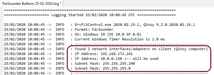
Please check that the driver is using the correct one! -
Another commonly reported problem is that network data is blocked by the Windows Firewall.
When this happens you may see that data does come in using other utilities (like the IO Tester or the manufacturer's own software), but that the Qinsy driver does not accept any data.
The following (Windows 10) steps may solve this:
-
Go offline, open the PC Settings (Start menu, Settings)
-
Select Windows Firewall (Update & Security, Windows Security, Firewall & network protection)
-
Select Advanced settings
-
Select Inbound Rules, highlight all 'Driver for Laser Scanning' entries and delete them using the right mouse popup menu (or Del key)
-
If you now go online, the Windows Security Alert message will pop up: It is important to check all three check boxes!
Real-time Performance Monitoring
When the scan data rate is too high, the other core Qinsy processes may not be able to handle the amount of data published by the driver (too many pixels/sec.) and in the past it would eventually crash the system.
An extra safety check has been implemented in order to prevent crashing of Qinsy: abnormal memory usage will be detected and when it exceeds a certain threshold limit a Stop command will be sent automatically to the scanner.
When that happens, the following message is displayed in the Events list in order to inform the user:
"SCANNING ABORTED"
"PROCESS MULTIBEAMER.EXE EXCEEDED CRITICAL MEMORY 1.7GB"
Whether such an event may occur is very much hardware dependent and/or on which settings are used.
You can check yourself if your setup is vulnerable: open the Windows Task Manager and monitor process Multibeamer.exe and/or DrvResultOut.exe while scanning. Under normal conditions the memory used by these processes should be constant.
If you notice that column Working Set (Memory) is constantly increasing, then the process will eventually crash when it exceeds 2GB and you will have to restart Qinsy. Note that 2GB is the maximum memory allowed for a 32bit process.
There may be situations that the default 1.7GB threshold is a little too low, or that the Stop scanning command must be sent earlier, e.g after exceeding a memory usage of 1GB.
So as an advanced user you may modify the following registry key in order to increase this threshold:
HKEY_CURRENT_USER\Software\QPS\QINSy\8.0\Drivers\DrvLaser\Settings\ProcessMemoryLimit
Note:
-
If you enter a value (in bytes) higher than 2GB it won't be accepted and the default will be used. You may try the following key value: 2000000000
-
If the value is set to zero, no monitoring of the Multibeamer.exe or DrvResultOut.exe process memory usage will be done. This is at your own risk because it may cause a crash when the memory usage exceeds 2GB.
But most important
Try to prevent having such events happening in your setup:
-
Check all your hardware and upgrade where possible. (Especially CPU power, Memory installed, Network card, Hard disk storage, etc.)
-
Read carefully the Improve Performance paragraph and try to follow up all the tips.