
Description
This driver decodes multibeam, sidescan, miscellaneous and external sensor data from the WASSP S3.
Driver Information
|
Driver |
ENL WASSP S3 |
Interface Type |
Freebase/TCP/IP |
Driver Class Type |
Freebase |
|---|---|---|---|---|---|
|
Yes |
Input / Output |
Input |
Executable |
DrvQPSFreeBase.exe WASSP_S3 |
|
|
Related Systems |
|
||||
|
Related Pages |
|
||||
Decoding Notes
This driver decodes multibeam, sidescan, miscellaneous and external sensor data from the WASSP S3.
Discovering the system
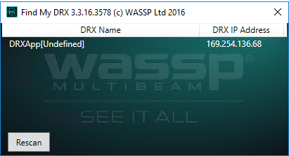
In order to configure the system in Qinsy, the IP address of the WASSP S3 unit is required.
The easiest way to determine the unit's IP address is to use WASSP's 'find my DRX tool' which will show the IP address of any WASSP S3 unit on the network:
Note
The IP address of the WASSP is by default set using DHCP or ZeroConfiguration.
According to the DRX installation manual "If there is a DHCP server on the LAN, the DRX will be assigned an appropriate IP address by the DHCP server. If there is no DHCP server, the DRX will fall through to Zero configuration assignment in block 169.254.0.0/16".
We have noticed that on some occasions, the IP address of the unit changed after a connection loss.
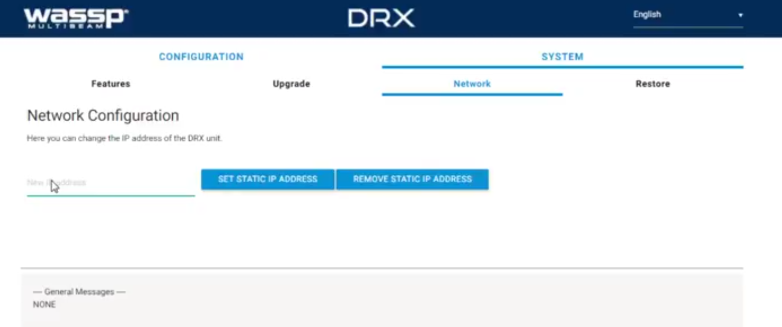
In order to prevent this, we recommend to set the IP address to a static value. It is possible to do this through the unit's web interface.
The option to set the IP address can be found under SYSTEM→Network
The section 'Configuration of the WASSP S3' provides more information about the web interface.
Configuration of the WASSP S3
The WASSP S3 can be configured using the system's web interface. This interface can be reached by browsing to the IP address of the system on port 2001. For instance, if the IP address of the system is 123.4.5.6, use "123.4.5.6:2021" as the URL in your browser.
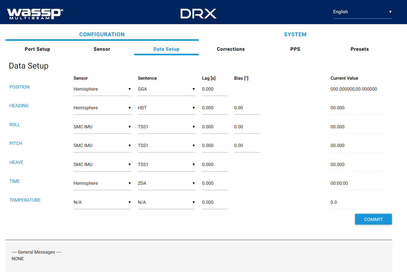
The web interface allows the user to configure the external sensors that are interfaced to the system such as motion and PPS (Time Synchronization).
More information on how to set up external sensors for the WASSP S3 can be found in the 'DRX Installation Manual'.
Note
Although Qinsy only decodes the raw bathymetry, make sure to interface a motion sensor to the system.
The system will not output any bathymetry data if no motion sensor is interfaced.
Database Setup
This driver decodes the following systems:
Bathymetry
Decoded from the 'Raw Bathy Data' message.
Sidescan
Decoded from the 'Sidescan Data' message.
External Sensor Data
The WASSP S3 system forwards external sensor data to Qinsy. In order for Qinsy to decode the data, the right format type has to be selected as the slot ID for the system.
Qinsy supports the following formats for external sensor data:
|
System |
Supported formats |
|
|---|---|---|
|
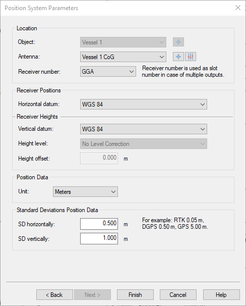
Position Navigation System |
GGA |
|
|
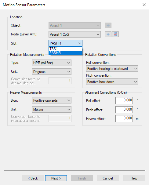
Pitch roll heave sensor |
TSS1, PASHR |
|
|
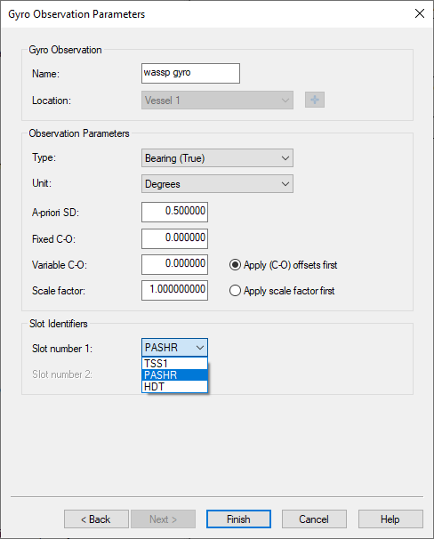
Gyro |
TSS1, PASHR, HDT |
|
Misscellaneous observations
|
Source message |
message field |
description |
slot ID |
|---|---|---|---|
|
PPS Status |
PPS Frequency detected |
Approximate detected frequency of PPS signal in Hz. |
PPS_FREQ |
|
PPS Jitter ms |
Milliseconds of jitter detected between internal DRX time keeping and external PPS pulse. |
PPS_JITTER |
|
|
PPS Status |
0 = Disabled
|
PPS_STATUS |
|
|
PPS Timestamp |
A nanosecond time stamp of last active edge of PPS pulse received.
|
PULSE_TIME |
|
|
Time Timestamp |
A nanosecond time stamp of last time sentence received.
|
MSG_TIME |
|
|
Sonar Status |
System Temp |
Temperature of system in degrees Celsius |
SYS_TEMP |
|
Transducer Temp |
Temperature of the transducer sensor in degrees Celsius |
TD_TEMP |
|
|
Ping Rate |
Current ping rate in pings per second |
PING_RATE |
|
|
Transmission Centre Frequency |
Current transmitter center operating frequency in Hz |
CNTR_FREQ |
|
|
Transmission Bandwidth |
Current transmitter bandwidth in Hz |
BANDWIDTH |
|
|
Ping State |
Indicates current state of transceiver
|
PING_STATE |
|
|
Sound Velocity |
Current sound velocity in meters per second |
SOUND_VELO |
|
|
Tide Value |
Current tide value in meters |
TIDE |
|
|
Link Speed |
Current Network Link Speed in Mb/s |
LINK_SPEED |
Time synchronization system
Decoded from the 'Time tag' message.
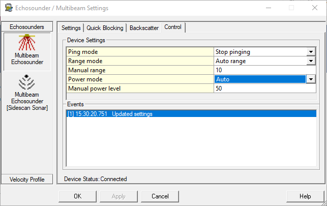
Control
A number of parameters of the system can be changed online. In order to access these settings open the 'Control' tab of the multibeam system in the Echosounder Settings dialog.
If you have configured a sidescan system, but not a multibeam system, the settings can be found in the Control tab of the sidescan system instead:
|
Setting |
Description |
|---|---|
|
Ping mode |
Stop pinging: The system will not ping. Auto pinging: The system will automatically ping. |
|
Range mode |
Auto range: The system will automatically detect the optimal ping range. Manual range: The ping range can be set manually. |
|
Manual range |
The range (in meters) to be used when the range mode is set to manual. |
|
Power mode |
No transmission: No pulse is transmitted (listen only). Auto: The system automatically determines the optimal power level to use. Manual: The power level is set manually. |
|
Manual power |
The power level (in percent, 0-100) to be used when the power mode is set to manual. |