
Description
This driver can be used to interface to the EdgeTech sonar systems via the Discover software.
The driver will decode data only and can not be used to fully control the sonar, but we do offer some options in Qinsy Online, i.e. simultaneously start and stop logging of JSF files with the Discover software from Qinsy. See 'Qinsy Online' tab page for more information.
The Discover software of EdgeTech is used for control. The data port to which the driver will connect should be selected in the Discover software. The default port is 1800, but for some systems it is 1900.
The driver will automatically connect to this port and receive data if sonar is pinging. Make sure that the computer or topside that sends the data to Qinsy is time synchronized via a Time Synchronization System (previously PPS System) otherwise the time stamping is unreliable. The Discover software should preferably run on the same computer as Qinsy to prevent timing issues. Driver will connect to both the data and control port. It is assumed that the data port is on a port number one higher than the control port; by default the control port is 1800 and the data port is 1801. Note that on some systems the default is 1900.
Warning
It is advised to interface all sensors (e.g. position and motion) directly to Qinsy even though EdgeTech has the option to forward all sensor data.
Driver Information
|
Driver |
EdgeTech |
Interface Type |
TCP-IP |
Driver Class Type |
Network |
|---|---|---|---|---|---|
|
Yes |
Input / Output |
Input/output |
Executable |
DrvEdgetechSocket.exe |
|
|
Related Systems |
|
||||
|
Related Pages |
|
||||
Decoding Notes
This driver supports numerous systems. Which systems can be decoded depends on the EdgeTech device that is used.
The table below shows the relationship between the device type and the systems that can be decoded by the driver.
|
|
41xx/42xx/43xx |
6205 |
4600 |
2000 series |
22XX |
|---|---|---|---|---|---|
|
Side scan |
|
|
|
|
|
|
Multibeam |
|
|
|
|
|
|
Position |
|
|
|
|
|
|
Pitch Roll Heave |
|
|
|
|
|
|
Gyro |
|
|
|
|
|
|
Under water sensor (Altitude, Depth) |
|
|
|
|
|
|
Sub bottom profiling |
|
|
|
|
|
|
Time Synchonization System |
|
|
|
|
|
|
Miscellaneous |
|
|
|
|
|
The following packets are decoded:
|
Message Type |
ID |
Contains |
Notes |
|---|---|---|---|
|
Sonar data |
80 |
Sidescan samples and some meta data |
The driver decodes JSF packets (id 80). If multiple packets are necessary to transfer a ping then the driver will concatenate the packets automatically on reception by looking at the ping number. Depending on the type of unit, decoded data may not contain a sound velocity value so make sure to select a manual sound velocity in Database Setup. |
|
Bathymetry |
3000 |
Travel time, beam angle, intensity, quality per sample |
Angles are with respect to the downward axis of the fish. The number of detections (beams) per ping can be variable (depending on processing settings in Discover).
|
|
Attitude |
3001 |
Heading, pitch, roll, heave |
Only decoded if flags in message indicate the presence of the field. |
|
Pressure |
3002 |
Absolute pressure, water Temperature, salinity, conductivity, Sound Velocity, depth |
Only decoded if flags in message indicate the presence of the field. |
|
Altitude |
3003 |
Altitude |
Only decoded if flags in message indicate the presence of the field. |
|
Position |
3004 |
Lat, long, height, time (for Time Synchronization) |
Only decoded if flags in message indicate the presence of the field, position will contain only lat-lon-height, no quality indication or fix mode. |
Timing
Make sure that a Time Synchronization System is defined in the Setup of the Qinsy Template DB file, so that the decoded ping time from the packets will be used as the observation time.
Without a Time Synchronization system the observation time will be the moment the data arrives on the port, which is incorrect.
Interfacing Notes
Make sure to use a proper network cable and proper setup of the TCP/IP network.
Network Settings
Discover and Qinsy on the same computer
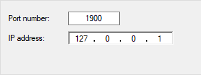
If the Discover software runs on the same computer as Qinsy, then the IP address is: 127.0.0.1. Usually the default port number is either 1800 or 1900.
Qinsy runs on a separate computer
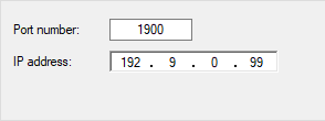
If Qinsy is run on another computer you will need to enter the IP address of the PC which Discover runs on.
Which is most likely the Top unit. ( So do not enter the IP address of the head )
Usually the Top unit's IP address is 192.9.0.99 with either port number 1800 or 1900.
System Configuration
Sidescan
The port number on which the Discover software will send data to Qinsy can be looked up in the Discover software through menu "Configuration|Network".
This will launch the following dialog:

Advanced: if necessary the default port and IP addresses can be modified in the Discover JNI configuration file. The Discover software program folder will contain multiple JNI files with a file name in the form DiscoverLast<device type>.jni. For instance "DiscoverLast4100.jni" is the settings file for the 4100 unit. To edit settings, the correct file for your system can be edited with any plain text editor.
Make sure that under header "[MessageTopsideCommand]" the host name is set to 0.0.0.0 and the port number to any number you require (default is 1800). Then check that under header "[MessageTopsideData]"the host name is also set to 0.0.0.0 and the port number is one higher than the control port.
Depending on the type of unit, decoded data (JSF packets id 80) may not contain a sound velocity value so make sure to select a manual sound velocity in Database Setup.
Multibeam
Port Number Setup
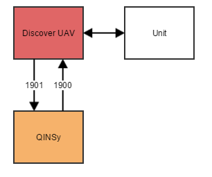
The port number which the Discover software will allow Qinsy to connect to is default set to 1900. This is the control port, the actual data will later, once the control connection is established, be transferred on the data port 1901.
It is possible to modify this port number if this is conflicting with other systems. Therefore the JNI configuration files as located in the EdgeTech folder can be modified. Look for keys "MessageTopsideCommand-Port" and "MessageTopsideData-Port" respectively.
Discover Software Setup
Start the Discover Bathymetric Software, assuming that the interfacing of the 6205/4600 is done correctly and Discover is receiving and showing data properly, go to menu Bathymetry|Basic Controls or Bathymetry|Advanced Controls to launch the setup dialog.
See screen capture of these dialogs below.
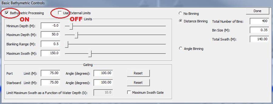
The Basic Controls allow the user to input the anticipated survey limits, control the filtering gates, and specify a binning method.
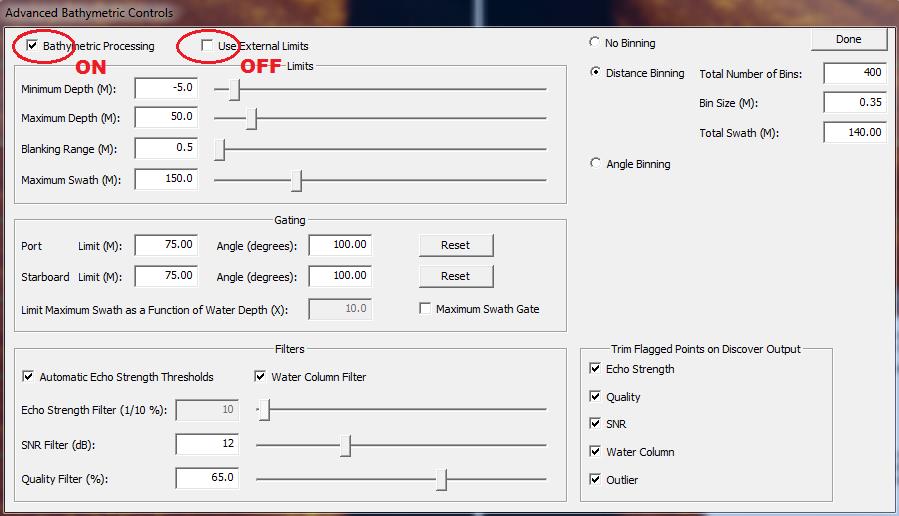
The Advanced Controls present the same functions as the Basic Controls, but also provide access to the filtering parameters built into Discover.
To log data with Qinsy, make sure that the "Bathymetric Processing" option is turned ON and "Use External Limits" is OFF. Qinsy will not set these ranges, so the user must set them up here. Fill in the anticipated minimum and maximum range and depth.
For the other bathymetry options please refer to EdgeTech 6205 or 4600 manuals.
Note that Bathymetric data filtering can affect the number of samples sent to Qinsy. If binning is fully enabled only 250 points per side will end up in Qinsy but depending on the binning options this may be more or less. Qinsy can process any number of points per ping (in principle unlimited) but database file sizes etc. may become quite large and ray tracing lots of samples can be CPU intensive.
Pressure to Depth conversion:
-
In theory the conversion from pressure to depth is dependent on the density of the seawater, but most people use something around 1.46 psi per m.
-
However, you also need to take out the atmospheric pressure (this is the 14.7 psi you are seeing when you look at the pressure value at 0m depth).
There is a “zero pressure sensor” button in Discover, under Control / External Device Controls, that allows you to take this out prior to deploying the tow fish (although in reality most people just leave this as is).
This atmospheric pressure offset is then used by Discover to calculate the depth from the pressure value.
Sub bottom profiling
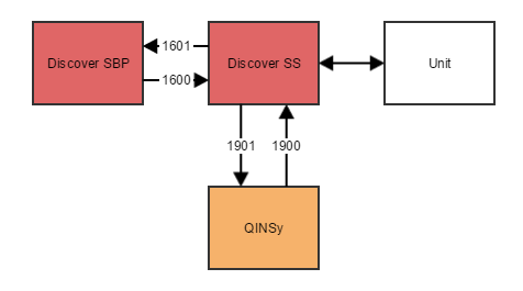
Discover SS
We refer to the Discover version that controls the sidescan part of the unit as "Discover SS" to make the distinction with "Discover SBP" more distinct.
The actual EdgeTech program has no such distinction and is simply called "Discover".
Note
The setup as described in this section will only function properly if you use Discover version 35.0.1.109 or up.
Sub bottom profiling is often used in combination with sidescan. This makes the setup of EdgeTech's discover software somewhat more difficult as you need to run two instances of Discover:
Unknown Attachment
In this setup Qinsy receives both sidescan and sub bottom profiling data on one port from Discover SS. The sub bottom profiler is controlled through Discover SBP.
Unknown Attachment
The port numbers shown here are the default port numbers. You can change them by editing the appropriate JNI file (see details in 'side scan' section above).
Look for the following tags in the file:
|
Communication channel |
Tag in JNI file |
Value in diagram |
|---|---|---|
|
Discover SBP to Discover SS |
[MessageSBTopsideCommand] |
1600 |
|
Discover SS to Discover SBP |
[MessageSBTopsideData] |
1601 |
|
Discover SS to Qinsy |
[MessageTopsideData] |
1901 |
|
Qinsy to Discover SS |
[MessageTopsideCommand] |
1900 |
Database Setup
Side scan
Add new system of type 'Sidescan Sonar' and select driver 'EdgeTech Sidescan'.
Set up proper IP address and port number of the EdgeTech computer or topside unit.
Driver specific settings
User definable gain
The EdgeTech sidescan signal can be rather low and may need some amplification in order to fit the Qinsy sidescan amplitude range of 0-65535 properly. The driver can apply a user definable scale factor to the amplitude data. Note that this is done in the driver so this will affect the raw data. Watch out for saturation because it can not be re-corrected in processing once the sidescan sample data that is recorded is saturated. The scale factors should be entered in Database Setup in the additional driver settings. Default gain is 1.0, this means no additional amplification.
|
Setting |
Options (bold=default) |
Description |
|---|---|---|
|
Model Number |
41XX/42XX/43XX
|
Choose 6205/4600 if you are using a bathy capable unit such as the 6205, 4600 or 220X series. In all other cases, choose '41XX/42XX/43XX' |
|
Extra Gain Port Low/Single Frequency |
Min = 0.1 Max = 10000 Default = 1.0 |
Additional gain applied to amplitude samples. |
|
Extra Gain Starboard Low/Single Frequency |
Min = 0.1 Max = 10000 Default = 1.0 |
Additional gain applied to amplitude samples. |
|
Extra Gain Port High Frequency |
Min = 0.1 Max = 10000 Default = 1.0 |
Additional gain applied to amplitude samples. Only used for multi-frequency systems |
|
Extra Gain Starboard High Frequency |
Min = 0.1 Max = 10000 Default = 1.0 |
Additional gain applied to amplitude samples. Only used for multi-frequency systems |
General Parameters
Take special care when selecting the sound velocity (SV) source. Some EdgeTech units have a real-time Sound Velocity Sensor (SVS) and this supplies a valid sound velocity with the sidescan data (the 6205 and 4600 units have this for instance). In that case, select "sound velocity from unit". If the unit does not have an SVS, select "use sound velocity" and enter a manual sound velocity to be used.
Channel Setup
On this page, add either two, four or six sidescan channels based on the number of frequencies supported by the unit. Use the slot numbers as described in the table below:
|
900 |
Port |
Auto detect |
|
901 |
Starboard |
Auto detect |
|
200 |
Port |
Low Frequency |
|
201 |
Starboard |
Low Frequency |
|
210 |
Port |
High Frequency |
|
211 |
Starboard |
High Frequency |
|
220 |
Port |
Extra High Frequency |
|
221 |
Starboard |
Extra High Frequency |
Auto-detect: In this mode it will pick either the low or the high frequency data, whichever is being utilized by the sonar. This will only work properly if only one frequency is used at a time.
Select proper node positions, you can define for every transducer a unique offset location and assign it here.
4100
The 4100 can only operate one frequency at a time so 2 channels will suffice when auto-detect slot number is used (see below).
Slot numbers
The slot numbers should be set properly or else no data will be decoded.
Multibeam
In order to decode the bathymetric data from an EdgeTech unit, two multibeam systems should be added to the template, one for port side and one for starboard side.
Add a new multibeam system, select driver "EdgeTech Bathy Port". Select same port and IP number as for the sidescan sonar. Select a node for the transducer acoustic center.
Mounting offsets should be zero because the down look angle of the transducer staves are already corrected for in Discover. Maximum number of beams can be left at 32768 beams.
On the last page you can leave the sound velocity observation for beam angles to disabled because the beam angles already refer to the proper sound velocity.
Add the second multibeam system, same procedure as above but now select multibeam driver "EdgeTech Bathy Starboard".
Sub bottom profiling
In order to decode Sub Bottom Profiling data from an EdgeTech unit, add an "EdgeTech Sub Bottom Profiling" system to the template.
Aside from the standard interfacing settings, the only thing that needs to be configured is the node of the SBP system.
Position
Add a new Position Navigation System, select driver "EdgeTech Position" and select same port and IP number as for the other drivers.
There is no requirement for the receiver number.
Motion
Add a new system of type Pitch Roll Heave Sensor, select driver "EdgeTech R-P-H", select same port and IP number as the other drivers.
On the Next page set the slot ID. The slot ID to use depends on the device type. For devices which support bathymetry (6205, 4600, 220X) set to "ATTITUDE". For other units use "PING_ATT".
Other settings should be:
-
Rotation Measurements: Type is HPR (roll first) and unit in Degrees,
-
Roll: Positive heeling to starboard,
-
Pitch: Positive bow up,
-
Heave: Positive upwards and Meters.
Motion Timing
Please note that EdgeTech does not apply any delay corrections to the data.
Qinsy presumes that the time tag supplied with the data is the correct time of the observation.
Therefore it is advisable, beside the motion decoding from the EdgeTech Driver, to interface the motion data directly into Qinsy and use the system related driver i.e. iXBlue TAH, Aplanix POSMV.
Gyro
Add a new system of type Gyro Compass, select driver "EdgeTech Heading", select same port and IP as the other drivers. The Slot number of the gyro observation should be set to "HEADING".
For Edgetech 4125 the Slot ID is still "HDG".
Motion Timing
Please note that EdgeTech does not apply any delay corrections to the data.
Qinsy presumes that the time tag supplied with the data is the correct time of the observation.
Therefore it is advisable, beside the motion decoding from the EdgeTech Driver, to interface the motion data directly into Qinsy and use the system related driver i.e. iXBlue TAH, Aplanix POSMV.
Underwater sensor
In order to decode Altitude, Pressure, ROV Depth and sound velocity an Underwater Sensor system should be added to the setup.
Select driver "EdgeTech Underwater Sensor". Select same Port and IP numbers.
Again the slot ID to use (and in some case whether or not an observation type is available) depends on if the unit is bathymetry capable:
|
Observation Type |
Unit |
Slot ID |
|||
|---|---|---|---|---|---|
|
Bathy capable |
Not bathy capable |
||||
|
ROV Altitude |
meter |
ALTITUDE |
3003 |
PING_ALT |
80 |
|
Pressure |
PSI |
PRESSURE |
3002 |
PING_PRES |
80 |
|
Sound Velocity |
meter/second |
SOUNDVELO |
3002 |
N/A |
|
|
ROV Depth |
meter |
FISHDEPTH |
3002 |
PING_DEPTH |
80 |
Miscellaneous
A couple of observations that do not fall into the other categories can be read as a miscellaneous observation.
These are:
|
Observation Type |
Unit |
Slot ID |
|---|---|---|
|
Water Temperature |
degrees Celsius/Centigrade |
TEMPERAT |
|
Salinity |
PSU |
SALINITY |
|
Conductivity |
micro-Siemens per centimeter |
CONDUCT |
Slot ID
Decoding will only work if the slot ID’s are entered properly and in CAPITALS.
Slot ID change
From Qinsy releases newer than June 2013 the slot ID names have changed to allow for supporting the 4600 system.
The Old slots ID's "ALT", "PRES", "HDG", "TEMP" and empty for Pitch/Roll are internally upgraded in the driver so they will still work.
For future setups the new ID's should be used.
Time Synchronization System
Warning
Make sure that a Time Synchronization System is defined in the template so that the decoded ping time from the packets will be used as the observation time.
Without a Time Synchronization System the observation time will be the moment the data arrives on the port, which is incorrect.
Online
Some settings of the EdgeTech units can be changed from the Controller. Please note you are still required to run Discover, even when changing the settings from Qinsy.
To view the control settings for the EdgeTech system, open the Echosounder Settings, select the sidescan system and open the 'Control' tab.
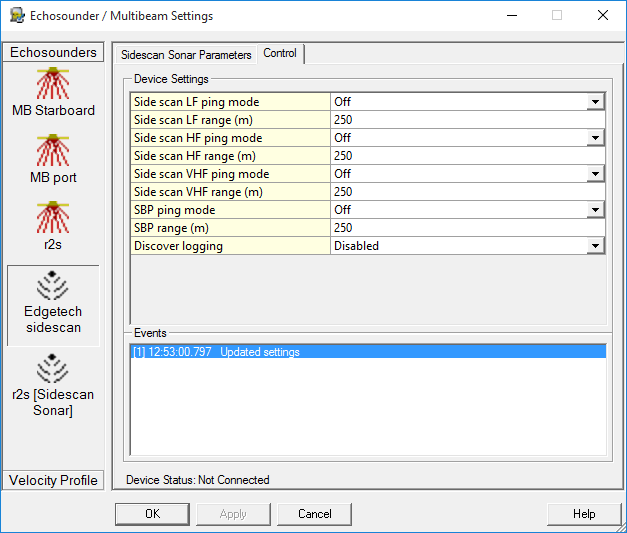
The offered settings are dependent on the type of sonar you are using
|
Setting |
Function |
Shown when |
|---|---|---|
|
Sidescan ping mode |
Enable or disable the pinging of a specific sidescan channel. |
Shown for each configured sidescan channel. |
|
Sidescan range |
Set the range of a specific sidescan channel. |
Shown for each configured sidescan channel. |
|
SBP ping mode |
Enable or disable the pinging of the sub bottom profiler. |
Shown if a sub bottom profiler system has been configured. |
|
SBP range |
Set the range of the sub bottom profiler |
Shown if a sub bottom profiler system has been configured. |
|
Discover logging |
Enable of disable logging (recording data) in Discover. For this to work, you will need to set up recording in Discover. |
Always. |
Info
The Control settings will only be available if a sidescan system has been configured.