
Description
Driver to read image data from a Klein 2000 / Klein 2100 / EdgeTech DF-1000 Sidescan Sonar System.
Driver reads buffered digital input, which is continuously output by the sonar system.
In order for the Qinsy PC to read this data a NuDaq PCI-7200 Digital I/O card must have been installed and configured correctly (see description under Interface Cards).
Driver Information
|
Driver |
EdgeTech DF-1000
|
Interface Type |
Serial |
Driver Class Type |
|
|---|---|---|---|---|---|
|
No |
Input / Output |
Input |
Executable |
DrvKlein2000.exe |
|
|
Related Systems |
|
||||
|
Related Pages |
|
||||
Decoding Notes
Which channel is decoded is determined by the channel setup of the Sidescan System in DbSetup. For every channel it is required to input a "Slot Id".
This must be set to a unique number which identifies the Channel in the digital data coming form the sidescan system.
The channel Id's (same for both Klein 2x00 and DF-1000):
|
Channel 0 |
Port Transducer 100 KHz |
|---|---|
|
Channel 1 |
Starboard Transducer 100 KHz |
|
Channel 2 |
Port Transducer 500 KHz |
|
Channel 3 |
Starboard Transducer 500 KHz |
So If you want to decode Port channel 100 KHz, make sure to enter Slot Id: 0.
Interfacing Notes
Klein 2000 Interfacing Notes
This driver requires a special, tailor made I/F cable that connects the PCI-7200 DIO Card port CN2 female 37 p Delta with the Klein 2000 Digital Output Port (also 37 p female Delta).
The cable has the following layout:
|
|
to Klein 2000 |
|
|
to PCI 7200 |
|---|---|---|---|---|
|
|
Digital o/p port |
|
|
dio card |
|
|
Male 37p Delta |
|
|
Male 37p Delta |
|
|
|
|
|
|
|
(LSB) |
Data Select 0 |
6 |
1 |
DI 0 |
|
|
Data Select 1 |
5 |
2 |
DI 1 |
|
(MSB) |
Data Select 2 |
4 |
3 |
DI 2 |
|
|
Trigger |
1 |
4 |
DI 3 |
|
(LSB) |
D0 |
19 |
5 |
DI 4 |
|
|
D1 |
18 |
6 |
DI 5 |
|
|
D2 |
17 |
7 |
DI 6 |
|
|
D3 |
16 |
8 |
DI 7 |
|
|
D4 |
15 |
9 |
DI 8 |
|
|
D5 |
14 |
10 |
DI 9 |
|
|
D6 |
13 |
11 |
DI 10 |
|
|
D7 |
12 |
12 |
DI 11 |
|
|
D8 |
11 |
13 |
DI 12 |
|
|
D9 |
10 |
14 |
DI 13 |
|
|
D10 |
9 |
15 |
DI 14 |
|
(MSB) |
D11 |
8 |
16 |
DI 15 |
|
|
|
|
|
|
|
|
Strobe |
2 |
19 |
I_REQ |
|
|
|
|
|
|
|
|
|
3 |
18 |
I_ACK |
|
|
|
3 |
37 |
I_TRG |
|
|
Ground |
3 |
36 |
GND |
Try to keep the cable length as short as possible, maximum length 6 metres but preferably shorter. Be careful with how you connect the cable, since both ends have the same connector. To prevent accidental swapping, mark the connectors clearly, failing to correctly connect the cable may result in damage to either system!
DF-1000 Interfacing Notes
The DF-1000 systems comes with a PCI I/O card that should be entered into a free PCI slot of the PC.
The schematic overview below shows the connection of the various parts. Most parts originate from EdgeTech; only the items marked with "QPS..." originate from QPS. For more information refer to DF-1000 manual.
The serial Com port of J6 can be used to send commands to and receive status info from the sidescan fish. The "EdgeTech Control Driver" can be used to control the sidescan operational settings, please refer to the chapter on this driver for more details.
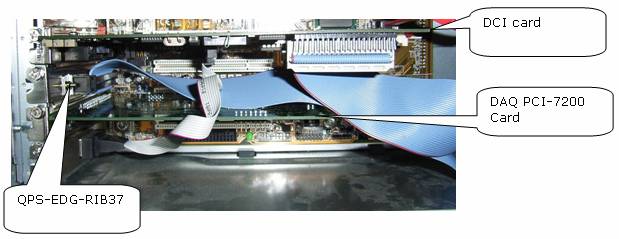
Picture above shows top view of opened Qinsy Acquisition PC with the necessary cards inserted. Note also the ribbon cable for the serial control port on the DCI.
Overview of QPS components
QPS-EDG-RIB37
37 Pins ribbon cable 40 pins female PCB header on one end, the other end connects to a 37 pins male delta connector. This delta connector is mounted on a PC-IBMAT-I/O bracket so it can be inserted in a free slot of the acquisition PC. Note that the pins 1-37 should be connected on the PCB header. Pin 1 can be identified by the red marking on the ribbon cable.
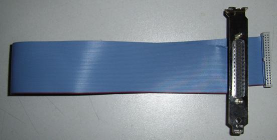
Image of QPS-EDG-RIB37
QPS-EDG-LOOPB-37
37 pins delta male to 37 pins female delta loop back cable. This cable connects the PCI 7200 Daq Card's 37 pins female connector with the 37 pins male connector of the ribbon cable. Note that this cable is not 1 on 1 wired, the wiring schedule can be found below.
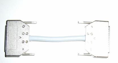
Image of loop back cable
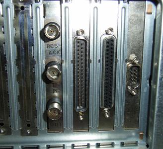
Back panel of PC: from left to right resp., the EdgeTech DCI board, the QPS-EDG-RIB37 connector and the QPS PCI-7200 DAQ card.
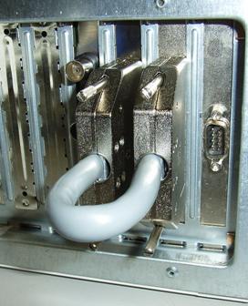
Same but with QPS-EDG-LOOPB-37 loop back cable attached.
System Configuration
DF-1000 Setup instructions
Jumper settings:
|
JP2 |
Set to Continuous output mode |
|---|---|
|
JP10 |
NMEA/1200 baud (Top Jumper 1-2 attached/bottom 3-4 removed) |
All other jumpers can be left to their default settings, they are not relevant.
RD wire bridge should be left to default (--RD)
Database Setup
No options are available for "old" mode.
A sidescan sonar will always be defined as an auxiliary system.
Drivers IO Notes
Command line parameter "DF1000" instructs the driver that the attached system is a EdgeTech DF1000 sidescan (The DF-1000 triggering works different).
Command line parameter "TST46" or TST366 indicates that instead of a "real" Klein 2000 system, the QPS Klein 2000 Simulator has been attached.
The difference between the two is that in the TST46 mode the swathlength of incoming swathlength is set to 46 milliseconds instead of 366 ms.
Make sure that the simulator is connected by the attached ribbon cable and NOT the official Klein 2000 I/F cable.
Command line parameter OLD_HF means driver will work in "old" mode and only decodes the 2 high frequency channels. OLD_LF means : low frequency channels, "old" mode.