Description
This driver with user-interface can be used to:
-
Control a Basler Industrial camera.
-
Automatically capture images to JPG files.
-
Update the image file meta information (EXIF) with GPS time and co-ordinates.
These captured and geo-tagged images (JPEG format) can be viewed using the Navigation Display, the Survey Manager, or Google Earth.
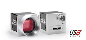
The driver was tested with the following cameras: Basler acA2500-60uc, AC1920-40UC. Other Basler cameras are expected to work but should be tested before purchase/deployment.
Typical application
A Basler camera is mounted on a vehicle, e.g. a car, and interfaced to Qinsy, together with a GPS receiver, a motion- and a heading sensor.
The Controller may for example generate a fix every 100 meters, triggering the Basler camera to capture an image.
All images are automatically stored in a user-defined folder on the Qinsy computer, updated with the exact location at time of capturing.
The image filename may also contain user-defined name specifiers, like project name, line name, position co-ordinates, sequence number, etc., in order to make further processing and archiving easy.
Driver Information
|
Driver |
DSLR Camera - Basler |
Interface Type |
USB3 |
Driver class type |
Freebase |
|---|---|---|---|---|---|
|
No |
Input / Output |
Input and Output |
Executable |
DrvBaslerCameraUI.exe |
|
|
Related Systems |
|||||
|
Related Pages |
|
||||
Issues
-
This driver is limited to a single camera per template database.
-
Basler cameras using the IIDC 1394, GigE Vision & Camera Link interfaces have NOT been tested but are expected to work. Customers are recommended to test before camera purchase and/or mobilization as no guarantees are given.
-
In case a customer uses this driver with a Basler camera which is different from the 'Basler acA2500-60uc' or 'AC1920-40UC' camera please inform QPS via JIRA so that we may update this documentation.
-
During the testing of this driver it was discovered that anti-virus software may influence the time it takes to grab an image. Please try disabling the anti-virus software in case grabbing an image takes too long.
-
This driver was tested with the following runtime version: 'Pylon 5 Runtime 5.0.5.8999'.
Runtime version
As mentioned above, this driver was created and tested with version 'Pylon 5 Runtime 5.0.5.8999'.
In case you use version 6.0 or newer, you might run into problems. In case you need this driver to work with a new version of Pylon, please reach out to support.
Interfacing Notes
Basler cameras may be connected to the Qinsy computer using one of the following interfaces:
-
USB3 Vision interface
-
IIDC 1394 interface
-
GigE Vision interface
-
Camera Link interface
It is recommended to use a Basler supplied cable to connect the camera. If possible connect the camera directly to the computer instead of via a USB hub or Ethernet switch. In case a USB hub is used it should be USB3.
It is important that the correct Windows drivers are installed for communication between your camera and the Windows operating system.
These drivers are normally supplied with your camera, or instructions on how to obtain them come with the camera's documentation. They may also be downloaded here from the Basler website.
Qinsy doesn't work yet in conjunction with the latest Pylon 6 version. Please use Pylon 5.0.12.11830.
You may use the following quick check in case a Basler camera with an USB3 Vision interface is used:
If you can see the camera using the 'pylon USB Configurator', then you can start the Controller to go on-line and proceed using this Qinsy driver without any (connection) problem.
The 'pylon USB Configurator' is part of the Basler supplied software.
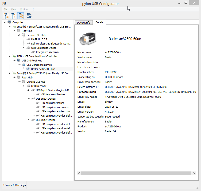
If you can not see the camera in the 'pylon USB Configurator', then there is no need to go online yet: you must first solve this problem.
Qinsy Configuration
Database Setup
Add an AIS System to Database Setup and select the "DSLR Camera - Basler" driver from the list.
No other interfacing settings are required, but make sure that there is already a successful USB3 or other interface connection. See tab page 'System Interfacing' for more information about this.
Note that this driver is handled internally as an AIS system, but no extra data is stored in the database during recording.
All on-line acquired images are stored as *.jpg files in a separate folder.
Online
Note
When the camera is (re-)connected while the Controller is already running, you may just start using it.
The driver should automatically find the camera.
The driver has user-interface and therefore will always be present in the Windows task-bar.
When going on-line for the first time, locate the driver and change the Node Setup and some default Options parameters:

The driver's dialog has an upper and a lower pane and four buttons in the middle.
The upper pane is reserved to show three different menus, a Node Setup, a Camera and an Options menu, which are accessible using the three menu buttons.
The lower pane is used for displaying all kinds of information, warnings and error messages. You may clear the entire message list using the [ Clear ] button.
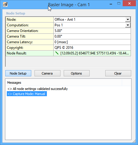
Driver Layout Menu: Node Setup
Select the button [ Node Setup ] to activate the Node Setup menu.
This menu is normally only needed during setup time. When finished, you may check the options in the 'Options' menu, or go to the 'Camera' menu.
Note there is no 'Apply' or 'OK' button in order to activate modifications, so changes will have effect immediately.
|
Node Setup |
|
|---|---|
|
Node |
Select the node location of the camera.
|
|
Computation |
Select the computation for the node location of the camera. |
|
Camera Orientation |
Enter the camera orientation, in degrees (0°..360°), relative to the vehicle's heading.
|
|
Camera Tilt |
Enter the camera tilt angle, in degrees (-90°..+90°).
|
|
Camera Latency |
Enter the latency in milliseconds. This is the time between the capture command send and the actual time of capture.
|
|
Copyright |
Enter your own free text. This copyright information will be stored as EXIF metadata. |
|
Node Result |
The current position of the selected node.
The indicator cycles when valid positions are received. Notice that without a valid position no images will be captured. |
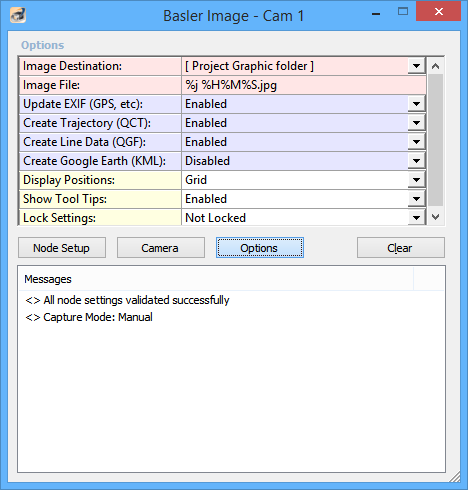
Driver Layout Menu: Options
Select the button [ Options ] to activate the Options menu
|
Options |
|
|---|---|
|
Image Destination |
Define where the captured images should be stored automatically.
|
|
Image Folder |
Use the button to browse for another folder than a sub-folder from the current project. |
|
Image Filename |
The name of the captured images. Notice that the extension will automatically be jpg.
|
|
Update EXIF (GPS, etc) |
It is highly recommended to be enable this option.
|
|
Create Trajectory (QCT) |
Enable to store a daily camera trajectory log file, in the project's Logfile folder.
|
|
Create Line Data (QGF) |
Store position of each captured image as point objects to a Line data (*.QGF) file.
This line data file is always located in the project's 'LineData' sub-folder and has the following name convention:
This file may be selected in the Navigation Display (View Properties, Layers, Line Databases) in order to show the exact location of each captured image as point object.
|
|
Create Google Earth (KML) |
Enabled to create a *.kml file with every captured image, in the same folder, with the same filename.
|
|
Display Positions |
The position results as displayed in Node Setup and Camera menu will be as Easting/Northing (Grid) or as Lat/Lon (Geo) on the WGS84 datum.
|
|
Show Tooltips |
When hovering the mouse over the left column rows, you will get some more information. Disable if this becomes annoying.
|
|
Lock Settings |
You may lock the user-interface settings, in order to prevent making changes by mistake. |
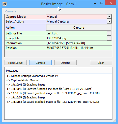
Driver Layout Menu: Camera
Select the button [ Camera ] to activate the Camera menu.
This menu should be active during normal operations:
|
Camera |
|
|---|---|
|
Capture Mode |
Select the capture mode for capturing images automatically:
|
|
Time Interval |
Enter the capture time interval in seconds, when capture mode is On Time.
|
|
Fix Interval |
Enter the capture fix interval, when capture mode is on fix.
|
|
When |
|
|
Select Action |
Notice that a selected action is only performed when using the Action button on the next row.
|
|
Action |
The action that will be performed depends on the Select Action setting on the previous row. See explanation above. |
|
Settings File |
Filename of the camera settings file which is automatically loaded during the startup phase of the driver. The selected camera settings file may be changed by using the button to select a different file.
The 'Pylon Viewer' program is part of the software which may be downloaded from the Basler web site. |
|
Image File |
Filename of the last captured image. Use the button to view the image with your default viewer. |
|
Information |
UTC Time and file size of the last captured image. |
|
Position |
Position co-ordinates of the last captured image.
|
Additional Information
Tips and Tricks
The following tips and tricks were written with all DSLR drivers in mind and some options therefore may not be applicable to this specific driver.
|
Performance |
Connect the camera with Power DC in, instead of running on batteries. This will normally also prevent the camera from going into sleep mode. |
|
Performance |
Use a solid state drive (SSD) as location for the image destination folder. |
|
Performance |
For Image Transfer use Move instead of Copy. |
|
Troubleshooting |
Always check that the camera, when connected via USB to your computer, is recognized by the Windows Operating system.
|
|
Troubleshooting |
When the camera is disconnected or switched off while on-line, you must go off-line and on-line again in order to re-establish a connection. |
|
Troubleshooting / Performance |
Capturing interval is too short in order for Qinsy to store the images to disk and trigger the next photo which results in missing photos.
|
|
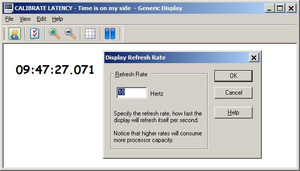
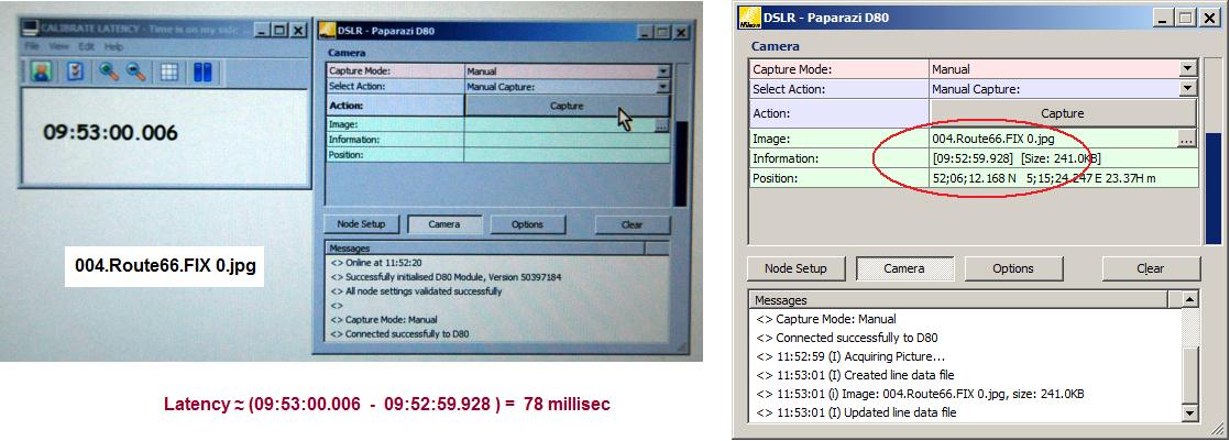
Calibrate Latency |
Notice that, due to the characteristics of digital cameras, there will always be a latency. This is the time difference between the moment of the capture command, and the timestamp of the captured image. The latency is often variable and depends on camera settings. E.g. if the camera is auto focusing, the latency can be up to 800 milliseconds! Under normal conditions the latency is small, around 100ms.
|
|
Camera Settings |
|