
Description
|
|
|---|
Driver for the CodaOctopus EchoScope real-time 3D sonar using a network connection (UDP). The driver will control the operational settings of the EchoScope and decode the ES2 UDP Data format that is transmitted by the EchoScope DIU software suite.
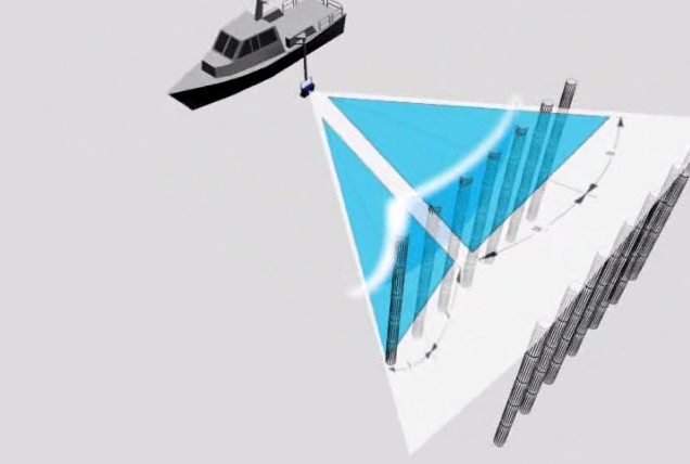
The EchoScope can ensonify an area of 50° by 50°, delivering 128 by 128 (16384) unique beams at a maximum update rate of 12 pings per second. The Echoscope is interfaced to the PC with an etthernet connection (for data) and a serial connection (for settings). However, Qinsy doesn’t communicate with the EchoScope directly but it will communicate with the DIU Software which will then forward commands and data to/from the hardware.
The driver connects via multicast address "234.5.6.7" to the DIU software on port 50323 for receiving data and 50326 for sending settings.
The "EchoScope DIU Software" should be installed on the same machine as Qinsy. Please contact Coda (support@codaoctopus.com) to obtain the latest version. Please read on to learn more about the DIU software.
The EchoScope system should be properly time synchronized to an external Time Synchronization (PPS) UTC clock. However at the time of writing this feature is still under development and the reported ping time may be 5-15 milliseconds wrong. This will lead to a small roll artifact but because of the great fore/aft opening angle it is expected that the ripples smear out in a sounding grid.
Version 1.8 of the "Echoscope ES2 UDP Data format Description" document was used to develop the driver. For more information on the format please contact CodaOctopus.
Note that Qinsy is capable of decoding and calculating all the footprints in real time at rates of over 200.000 beams per second, but proper modern PC hardware is required. Tests showed that CPU load is very low using an Intel I7 CPU based computer. If your PC hardware can not cope with the number of beams then the beam reduction option of the driver may be used to lower the decoded number of beams in the driver. Note that since this will be done at driver level the beams will not be recorded in the database either. See below how to activate the reduction.
(June 2014) a dual Frequency Echoscope can only be operated from Coda Octopus Survey Explorer Software. But the data can still be read and logged in Qinsy.
Currently (July 2018) software from Coda has been changed and it is likely that with the current version this driver will not work.
Driver Information
|
Driver |
CodaOctopus Echoscope |
Interface Type |
UDP/IP Client |
Driver Class Type |
UDP |
|---|---|---|---|---|---|
|
Yes |
Input / Output |
Input |
Executable |
DrvEchoScope.exe |
|
|
Related Systems |
|||||
|
Related Pages |
|
||||
Decoding Notes
The time tag from the data packets is always decoded and used.
Per beam the driver will decode a range in centimeters (converted to travel times assuming a fixed 1500 m/s) and an Intensity Value between 0-32768.
The Beam and Tilt angles are calculated by the driver using the start and end angles that are provided in the ES2 message.
Quality is not used. Beam angles are with respect to a sound velocity of 1500 m/s.
For proper tilt and beam angle convention you should always set in DIU Setup the "Sonar Head Axis Direction" to "C".
System Configuration
DIU Software Info
The CodaOctopus EchoScope DIU software consists of several programs that are started by the main program called the “Orchestrator”. When started, this program will launch the other required programs. They are all started in minimized mode. Their icons can be found in the system tray (next to the Windows clock) in the lower right hand corner. Once properly configured, the applications will not require any intervention from the user, but for debugging communication problems they can come in handy. The Orchestrator will have to be started prior to running Qinsy so it is advised to either use a batch file to start Qinsy with and add the Orchestrator program in it too or to place a shortcut of the Orchestrator in the Windows startup folder.
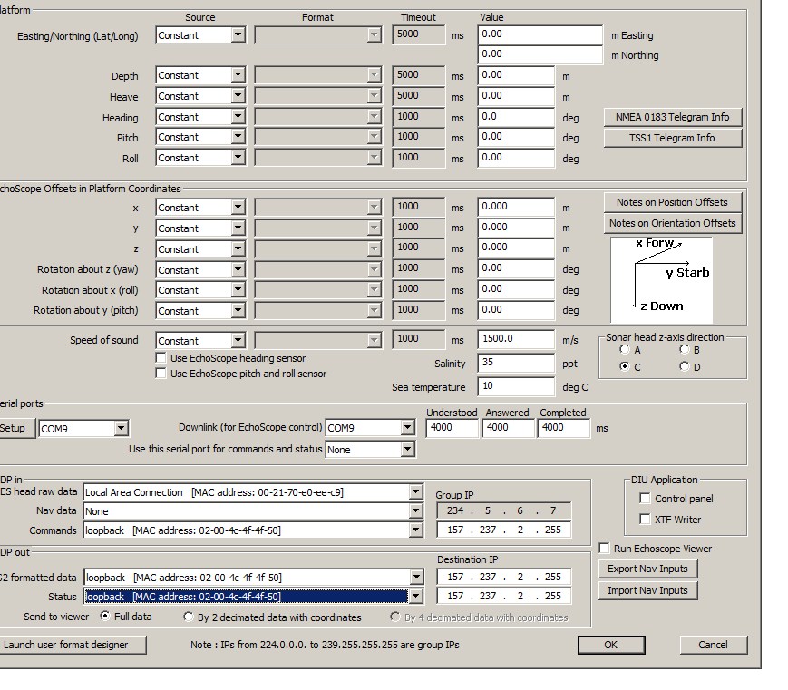
The DIU software needs to be properly set up with the DIUSetup program just once. The setup that worked during the test will be shown below but there may be other ways to interface the two programs.
Note: This software may be subject to change in the near future by Coda Octopus but the basic principles will stay the same.
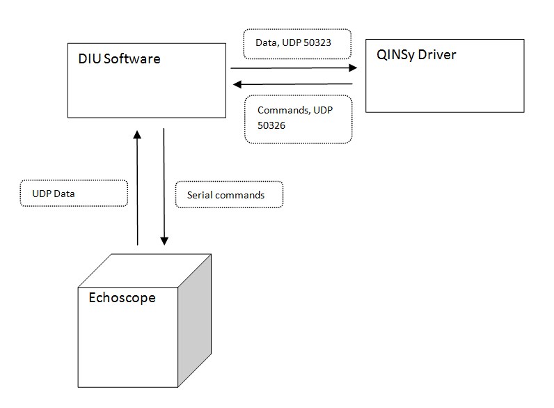
Basic Architecture Qinsy <-> DIU software
In the past a "Microsoft Loopback Adaptor" was required but this is no longer necessary because the driver now supports multicast.
Set up the DIU Software
Run the DIU Setup program just once to set up the interfacing between the head, the DIU software and Qinsy.
Start the DIUSetup program from the Start menu CodaOctopus|Echoscope DIU Software. Note that since version 4.9 this uses a "wizard style". Note that this wizard is subject to change.
The Settings should be:
1 - How to communicate with Echoscope?
Select the appropriate network adaptor and the serial port to which the Echoscope is connected.
2 - How is your vessel navigation & attitude data provided?
Not important for the Qinsy interface, select anything you find appropriate.
3 - How is your Echoscope oriented?
For now this should still be "Position C" otherwise the beams will not be calcualted properly.
4/5 - Offsets.
This does not affect the ES2 Raw data, so select anything you find appropriate.
6 - Do you want to enable Remote Control?
Should be "Yes" even though it runs on the same computer. Select the appropriate network and Full Echoscope data.
7- Do you want to define a Coordinate Reference System?
This does not affect the ES2 Raw data, so select anything you find appropriate.
8- Apply the settings here.
The driver connects with the DIU software via a multicast address of "234.5.6.7". This is hard coded and can not be changed.
Database Setup
Multibeam Echosounder
Add a new Multibeam System, Select CodaOctopus Echoscope driver. Set the IP Address to the PC's network adapter you use for communication with the DIU software.
This is the same address as selected on page 6 of the DIU setup wizard. Set the Port number to 50323.
The EchoScope delivers 16384 beams per ping so the "Max. beams per ping" value should be at 16384.
Set the "Transducer Setup" to "Assume Common Acoustic Center". The acoustic center of the EchoScope is the center of the receiving area.
See also the image below.
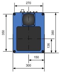
Acoustic center of the EchoScope Transducer.
When the transducer is mounted horizontally with the transducers facing downwards, and the connectors are pointing to the bow, the Multibeam Pitch/Roll/Heading Mounting Offsets in Qinsy should be set to 0°-0°-0°.
When the transducer head's connectors points to port the Heading Offset should be around -90° and when pointing towards starboard this should be about +90°.
Furthermore the transducer will always be tilted. When the transducer is tilted upwards, e.g. the connectors are lifted higher than the other end, the Pitch offset as entered in Qinsy becomes positive.
Note that roll will be around zero.
For usage with the Universal Mount as delivered by Coda the following mounting angles are commonly used for surveys:
|
pointing to |
mount pole position |
Roll Offset |
Pitch Offset |
Heading Offset |
|
port |
C17 |
0 |
+37.5 |
-90.0 |
|
port |
C16 |
0 |
+52.5 |
-90.0 |
|
port |
C15 |
0 |
+67.5 |
-90.0 |
|
starboard |
C17 |
0 |
+37.5 |
+90.0 |
|
starboard |
C16 |
0 |
+52.5 |
+90.0 |
|
starboard |
C15 |
0 |
+67.5 |
+90.0 |
On the last page of the multibeam system wizard select the Sound velocity observation for the beam angle correction.
U/W Sensor - Sound Velocity Observation
The EchoScope uses a sound velocity of 1500 m/s for its beam steering. So in order to carry out accurate surveys with the unit, the beam angles should be corrected with the actual sound velocity measured by the head prior to ray tracing. This recalculation will take place in Qinsy as long as the proper “Underwater Sensor” with sound velocity observation is assigned. A manual Sound Velocity System/observation should be defined whenever a real sensor is not interfaced. Failing to do this will result in an error in the final footprint that will increase when the actual sound velocity deviates further from 1500 m/s.
Online
Note: prior to going online with Qinsy, make sure the DIU software is configured and running.
The operational settings of the EchoScope can be changed by Qinsy through the Controller-Echo Sounder Settings dialog, Control Tab.
Various settings can be changed; refer to Coda documentation for more information on what these settings mean and the consequences of changing them.
Some parameters are fixed like the resolution and pulse length, these can not be changed as they are hard coded.
|
Settings |
Description |
||||||||
|---|---|---|---|---|---|---|---|---|---|
|
Initialize Head |
When Qinsy is started the settings are all disabled and you should send the "Init Head" command first to the EchoScope. This will also send all the settings to the EchoScope because the head will not remember them when powered up. Select from:
INIT Now - when first connecting to an Echoscope, it is necessary to initialize the Echoscope to ensure that all parameters in the head are set. Commands are sent to initialize the Echoscope head after first powering on. |
||||||||
|
Minimum Range |
Sets the minimum range. |
||||||||
|
Maximum Range |
Sets the maximum range. |
||||||||
|
Detect Mode |
This command can be used to switch between
|
||||||||
|
FAT Threshold |
First-Above-Threshold: Sets the threshold value used in the beam detection algorithm. The value is in A/D units (i.e. a number from 0 to 65535).
FAT Mode is used to adjust the sensitivity, clutter, transmit, receive, and threshold to sharpen the image. |
||||||||
|
Sensitivity |
Sets/gets the intermediate gain - i.e. the gain between pass I and pass II in the beam former. This should normally be 13. The following options are available:
|
||||||||
|
Auto Gain |
Set to either ON or OFF. |
||||||||
|
TX Gain (dB) |
Sets the transmit power gain - i.e. the projector output level.
|
||||||||
|
RX Gain (dB) |
Sets the Voltage Controlled Amplifier (VCA) value used for the receive gain.
|
||||||||
|
Side-lobe Clipping |
This command is used to set the side-lobe clipping performed on a range-slice by range-slice basis.
Valid parameters for the command are: 1 – 6dB
|
||||||||
|
Receiver Shading |
Set to either ON or OFF.
|
||||||||
|
Ping Rate |
Causes the Echoscope to ping 'n' times where the first ping is numbered <ping number>. If no <ping number> is specified, the last ping number will be incremented by one and be used.
Sets the effective ping mode for system. When the Ping Mode value is 0, the system is in software trigger mode and will only trigger when sent a ping command.
|
||||||||
|
Beam Reduction |
Sets the decimation of ping recording by supplying a rate value 'r'. 1 in 'r' pings are recorded to file, so a value of 1 means to record all pings. Select from:
|
||||||||
|
Along Fan Reduction |
The fore/aft beams are clipped away by the driver. Select from:
|
||||||||
|
Across Fan Reduction |
The port/starboard beams are clipped away by the driver. Select from:
|
Note
When the EchoScope is used in combination with an old PC it may be necessary to reduce the number of beams that are decoded by the driver to relieve the strain on the system caused by the calculation and ray tracing of the footprints.
This will come at a price of course: lower resolution, but since there is so much redundancy in the measurement this will not be a problem.
The reduction options are not settings that are transmitted to the EchoScope but are local driver settings.
The driver can optionally reduce the number of beams in three ways:
1) Global beam reduction e.g. every 2nd beam is kept or every 3rd beam is kept etc.
2) Along Fan reduction, e.g. Off, 40°, 30° , 20° etc. the fore/aft beams are clipped away in the driver.
3) Across Fan reduction, e.g. Off, 40°, 30° , 20° etc. the port/starboard beams are clipped away in the driver.
Remember that the terms"fore/aft, and port/starboard" apply to a transducer that points forward, mounted with zero heading offset.
It is important to remember that when the driver beam reduction is enabled the beams that are clipped are not recorded in the database.