Centre Source Position (CSP or CMP) - 12
Description
This driver has user-interface, and is therefore always present in the Windows taskbar, when on-line.
It will calculate a "weighted mean" position from a user-definable list with node positions. The user may give a weight for each selected position. Several methods can be selected to calculate the horizontal and vertical components.
Example of a simple scenario:
The user has an ROV object, positioned by USBL.
In the past you had to create a setup with a loopback cable and an extra output and input driver, to get the calculated ROV position stored in the recorded database. This is not necessary anymore, just select this driver in your setup, and select online the ROV object in the driver's position list.
Example of more complicated scenario:
The user has a vessel that is towing a fish, the fish is towing a centre buoy and the buoy is towing a tail buoy. All these objects are positioned independently, e.g. with USBL. With this driver you can calculate a point somewhere along this chain, e.g. the center of a virtual electromagnetic source.
Further, the driver takes care of the following situation:
When the towfish is lowered, the other towed object (inclusive the "virtual" center source) will normally follow with a delay. The vertical component for the calculated center source position will be corrected for this delay. All depends on the user-definable settings.
Driver Information
Driver | Centre Source Position | Interface Type | Serial | Driver Class Type | Freebase |
|---|---|---|---|---|---|
No | Input / Output | Input (User Interface) | Executable | DrvCentreSourcePosition.exe | |
Related Systems |
| ||||
Related Pages | |||||
Database Setup
Add a new system to your database template of type Positioning System, and select the driver "Center Source Position".
No I/O parameters are needed.
IMPORTANT
Select on the 2nd page of the wizard for Horizontal and Vertical datum: Survey Datum.
Purpose
This driver is meant to position the centre of the source (CS), using sensor and position information from head and tail object(s).

The following will describe a procedure using only two USBL Transponders; but more nodes can be used.
Online
The driver will have UI and always present at the windows taskbar when being on-line.
It will gather all available sensor/computation information to calculate a position for the CS. This position will be passed, just as any other positioning driver, to all other Qinsy components, e.g. to Computation 3. It will also be recorded in the database during logging.

So, in Qinsy there will be (at least) three objects defined in the Db Setup, a Head object (for example a towfish), a Tail object and a CS object.
Notice that the Head and Tail object(s) are physically towed behind the vessel, the Centre Source object is a virtual point at a certain distance from the head and tail object(s).
Three computations will be defined in the Controller:
Computation 1: The Head object, this will be positioned normally:
(Vessel DGPS/Heading/VRU, USBL data to Td1, Bathy Depth, Kalman Filters, etc…)Computation 2: The Tail object, this will be positioned normally:
(Vessel DGPS/Heading/VRU, USBL data to Td2, Kalman Filters, etc…)Computation 3: The CS object, positioned using data from the new driver.
Two methods may be used to calculate a horizontal position of the CS and two methods to calculate the vertical component.
Horizontal position
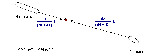
Method 1: “Interpolated”

The CS position will be the weighted mean of the Head object position and the Tail object position. The weights are derived from the ratio of the given distances.
L is the calculated length; d1 and d2 are the given distances (manual user input).
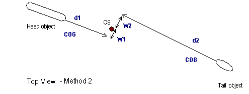
Method 2: “Weighted Mean Position Vectors”

First, for each separate object there will be a CS position calculated, using its vector.
Distance d1 and d2 are given (manual user input). The rotation can be object’s heading or object’s COG (manual user selection). Notice that when object’s heading is not available, automatically COG will be used.
Then the final CS position will be the weighted mean of all these CS’ positions, using the weights from manual user input.
Vertical Component
Method 1: “Interpolated”
When the horizontal position is calculated, using one of the above described methods, the height value is also a result of the weighted mean.
It is this height that will be used when method 1 is selected.
Method 2: “Follow Primary Object”
First, the user must designate among the list of positions a primary object. Normally the primary object will be the one that also contains a bathy sensor.
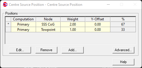
Use the right-mouse popup menu to make the selected position primary. It will have an asterix “*” in the list (see the example of the new driver above).
CS Height = Height Primary Object (at CurrentTime – Delay) + Z-Offset
The Z-offset and Delay are manual input.
If the delay is zero seconds, the height of the centre source object will follow exactly the height of the primary object.
