Description
The center crane position driver is typically used on backhoe cranes, working stationary on land, equipped with an RTK GPS positioning system, but no heading sensor.
The idea is as follows: The crane, when being stationary, should rotate one time 360 degrees. By collecting all the RTK positions during the circle turn, the driver will calculate the center position of the circle, using a so-called least square adjustment.
When finished, it will then feed this center crane position into the Qinsy system, so Qinsy can calculate a bearing between the fixed center position and the real RTK GPS antenna. The crane operator may start working, until the crane needs to be moved to a new work location. When arrived at the new location, a new center crane position must be calculated, again by turning the crane one time 360 degrees.
Driver Information
|
Driver |
Centre Crane Position |
Interface Type |
Serial |
Driver Class Type |
Freebase |
|---|---|---|---|---|---|
|
No |
Input / Output |
Input (User Interface) |
Executable |
DrvQPSFreeBaseUI.exe CRANE_POS |
|
|
Related Systems |
|||||
|
Related Pages |
|
||||
Database Setup
Assumption is that the real RTK GPS system has already been added to the template and its antenna offset.
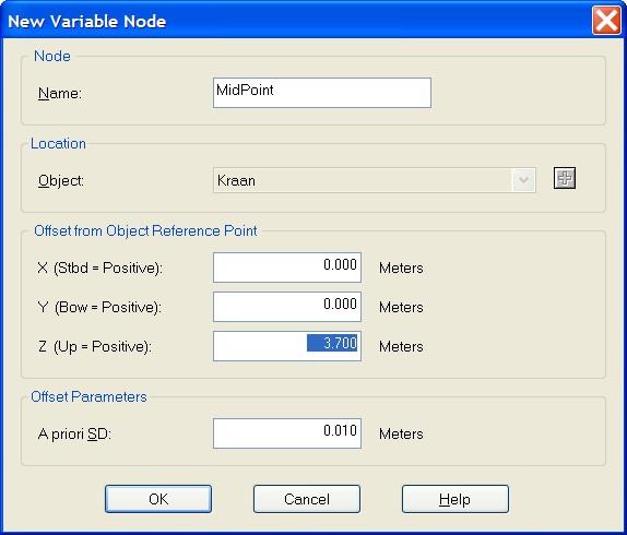
First, add a new variable node, the turning center point of the crane.
This turning point is most likely also the reference point, however, we can not use this one. So add a new one, you may leave the X and Y offset zero, but the Z-offset should be the same as for the real RTK GPS antenna.
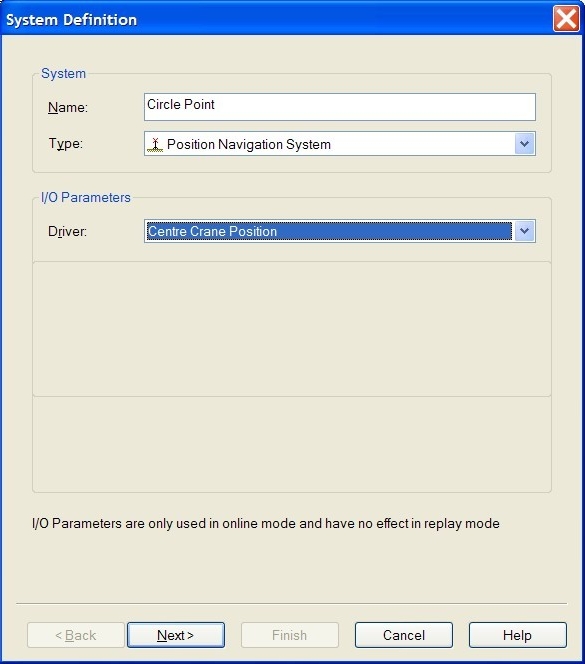
Then, add a new Position Navigation System, and select the "Center Crane Position" driver from the long list. Of course, no I/O parameters are needed.
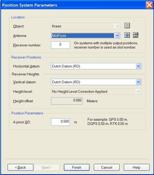
More important are the settings on the next wizard page: Select the object and the new added antenna node.
The receiver number is not used, you may leave this to zero, however, the horizontal and vertical datum setting is important: Select here your survey datum.
Online
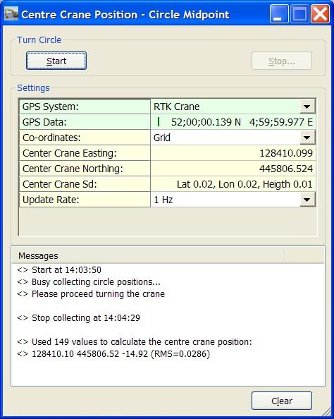
The driver has user-interface, and therefore will always be present in the Windows taskbar.
When going on-line for the first time, locate the driver, and change the GPS System setting from [Manual] to your real RTK GPS system.
If all is okay, GPS Data should be coming in on the second row, and the icon in front of it rotates on every received update.
Tip: You may hoover the mouse over the left column rows, in order to get some more information.
Description of the Turn Circle buttons:
|
[Start] |
When GPS Data is coming in as expected, hit the start button, confirm with OK and start rotating the crane 360°. While doing this, the driver will collect all GPS data, until you hit the stop button.
|
|
[Stop...] |
As soon as the crane operator completes the turn, press the Stop button, and confirm with Yes. A new center crane position will be calculated. It co-ordinates will be displayed immediately in the settings fields, and updated into the Qinsy system. |
Description of the Settings:
|
GPS System |
The first entry is always [Manual]. The other entries are the available GPS systems (probably one). Select [Manual] if you know already the exact co-ordinates of the center crane position. These co-ordinates should then be entered as easting/northing, or as latitude/longitude in the fields below. |
|
GPS Data |
This row is only visible when a real GPS system is selected. It shows the raw data from the selected GPS system as Latitude and Longitude. These values can also be seen in an Observation Physics Display. Every received update you will see the icon rotating. If this icon has stopped rotating, no GPS data is coming in |
|
Co-ordinates |
Set to Grid if you want to see (or update) the Center Crane position as easting/northings. Set to Geo if you want to see (or update) the Center Crane Position as Latitude/Longitude. The format of the geo co-ordinates depends on the Global Geographical format settings, which can be changed in the Console. |
|
Center Crane Easting |
The easting of the Center Crane position on Survey Datum. Only visible when the Co-ordinates setting is set to Grid. The number of decimals depends on the Global Resolution setting, which can be found in the Console. Shows [n/a] if no Center crane position has been calculated yet. This field is only editable when the GPS System is set to [Manual]. |
|
Center Crane Northing |
The northing of the Center Crane position on Survey Datum. Only visible when the Co-ordinates setting is set to Grid. The number of decimals depends on the Global Resolution setting, which can be found in the Console. Shows [n/a] if no Center crane position has been calculated yet. This field is only editable when the GPS System is set to [Manual]. |
|
Center Crane Latitude |
The latitude of the Center Crane position on Survey Datum. Only visible when the Co-ordinates setting is set to Geo. Shows zero's if no center crane position has been calculated yet. This field is only editable when the GPS System is set to [Manual]. |
|
Center Crane Longitude |
The longitude of the Center Crane position on Survey Datum. Only visible when the Co-ordinates setting is set to Geo. Shows zero's if no center crane position has been calculated yet. This field is only editable when the GPS System is set to [Manual]. |
|
Center Crane Sd |
The Standard Deviation (Sd) for the Latitude, the Longitude and the Height of the calculated Center Crane Position. These values are a results of the least square adjustment. The lower the values, the more accurate the Center Crane Position is. The values are not visible when the GPS System is set to [Manual] |
|
Update Rate |
The update rate for the Center Crane Position, which goes into the Qinsy system. The value is default set to 1Hz, meaning every second. If you set to [None], no position will be updated, and the Computation using this Position will stop. It is recommended to use the same update rate as the update rate of the selected GPS System. |
|
[Clear] |
The last 200 history messages are displayed in the message view. Use the clear button to empty the list. |
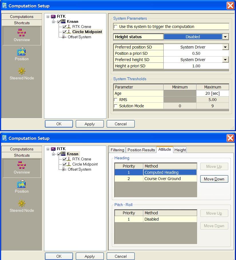
Controller Setup
In the computation setup, you need to enable both positioning systems, the real RTK GPS system, and the Center Crane Position system. Use the RTK GPS System as triggering system. It is recommended to disable the height status for the Center Crane Position system. Click on the object, go to the attitude tabpage, and make sure that the Computed Heading has priority no. 1.
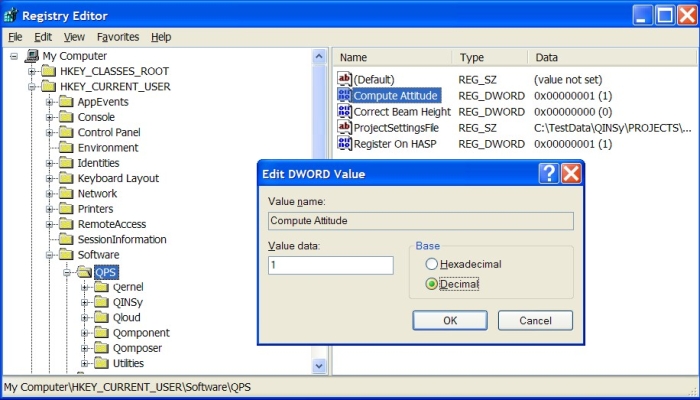
Registry Options
Make sure that the following advanced registry key, 'Compute Attitude' has the value 1. This value is default set to 0, after a clean Qinsy installation. Once you changed this value, it will stay 1, so you only have to check/change this registry key setting once.
Go to Windows Start, Run..., and enter command 'regedit'.
Locate in the tree key 'HKEY_CURRENT_USER\Software\QPS'.
Then, double-click in the right-pane on value name 'Compute Attitude'. If the value data is 0, change it to 1.