
Description
This driver, with user-interface, is used to decode messages from a CDL MiniPOS3 system, a high grade Inertial Navigation System (INS).
The MiniPOS3 system, usually mounted on an ROV, provides high accuracy aided positioning from a variety of external sensors including GPS, DVL and Acoustics, i.e. USBL and/or LBL.
The system will output (by means of a so-called Navigation message) the following observations, which can be decoded by this driver:
-
Heading
-
Attitude (Roll and Pitch)
-
Position (Lat, Lon, Depth, Altitude)
-
Velocities (North, East, Down direction)
-
Acceleration (X, Y, Z directions)
-
Rotation rate (X, Y, Z Axis)
-
Sensor Status and Monitoring
In order to enhance the aided position this driver will also send information to the MiniPOS3 system by means of a so-called USBL Position message.
Notice that receiving data from, and sending data to, is done via the same serial COMport. (See the System Interfacing tab.)
Driver Information
|
Driver |
CDL MiniPOS3 (Binary) |
Interface Type |
Serial |
Driver Class Type |
Terminated |
|---|---|---|---|---|---|
|
Yes |
Input / Output |
Input |
Executable |
DrvQPSTerminatedUI.exe |
|
|
Related Systems |
|
||||
|
Related Pages |
|
||||
Interfacing Notes
-
Navigation message
When the MiniPOS3 unit is also interfaced with an external PPS/GPS input (Aux2/GPS port), then it may be useful to use the time from the incoming message in order to time stamp the data.
This can be achieved when the following criteria are met:-
Your template setup has a valid PPS system
-
The so-called 'UTC' driver is selected (See Drivers.io Options below)
-
Control bits 'UTC Latency' and 'Latency Compensation' are set to True (See Online Setup, General Setup below)
-
-
USBL Position message
The time inside the outputted message will be the exact time for the computed ROV node position.
In case option Deskew ROV Node Output is enabled, then it will be the exact moment of output.
-
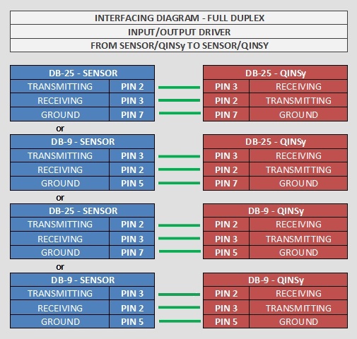
COMport
Outputting the USBL Position message to the MiniPOS3 system goes via the same serial COMport as the incoming Navigation message; therefore one should take the following full-duplex wiring diagram into account when using I/O cables and connectors:
Database Setup
In order to decode the position from the system, add a Position Navigation System to the template and select driver "CDL MiniPOS3 (Binary) Position".
On the second wizard page, select for Horizontal Datum 'WGS84', but for Vertical Datum select the Mean Sea Level Model (because the height will be derived from the decoded depth, with a negative sign). However, it is highly recommended to set the Height Status to 'Unreliable' in the on-line Computation Setup, in combination with the use of an ROV Depth observation (see below).
In order to decode the heading from the system, add a Gyro Compass System to the template and select driver "CDL MiniPOS3 (Binary) Heading".
Use the same I/O parameters (COMport, baudrate, etc.).
In order to decode the pitch and roll (there is no heave) from the MiniPOS3, add a Pitch, Roll and Heave Sensor System to the template and select driver "CDL MiniPOS3 (Binary) R-P-H". Use the same I/O parameters.
Notice that the exact pitch and roll conventions (second wizard page) are not known at the time of this writing.
In order to decode a depth observation from the MiniPOS3, add an Underwater Sensor to the template and select driver "CDL MiniPOS3 (Binary) Depth & Altitude". Use the same I/O parameters.
On the second wizard page, add an ROV Depth observation. Select for At Node the correct node on the ROV object.
You may also decode the altitude (or height above bottom) which comes directly from a valid Doppler input into the MiniPOS3:
Add an ROV Altitude observation, and select for the At Node the bathy sensor location on the ROV object.
The units on the last wizard page must be Meters.
Notice that this type of observation is not used by the Computation Setup, but it will be decoded, displayed and stored.
In order to decode velocities, accelerations along and rotation rates around the three axes, add an Acceleration Velocity Sensor system to your database and select the driver "CDL MiniPOS3 (Binary) Velo, Acc, Rot". Use the same I/O parameters.
Add the following observations on the second wizard page: Velocity (Easting Speed, Northing Speed and Vertical Speed), Acceleration (X, Y and Z) and/or Rate-Of-Turn (X, Y and Z).
On the next wizard page, select for the velocity observation unit: Meters / Second, for the acceleration observations: Meters / Second^2, and for the rate-of-turn select Degrees / Second.
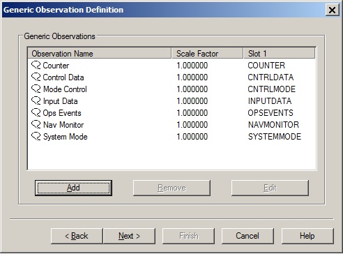
In order to decode status information from the MiniPOS3, add a Miscellaneous System to the template and select driver "CDL MiniPOS3 (Binary) Status". Use the same I/O parameters.
On the second wizard page, add the following seven Generic observations:
Observation representing the System Mode, with Slot ID 'SYSTEMMODE'
Observation representing the Navigation Monitor, with Slot ID 'NAVMONITOR'
Observation representing the Operational Event Flags, with Slot ID'OPSEVENTS'
Observation representing the Input Data Validity Logicals, with Slot ID 'INPUTDATA'
Observation representing the Mode Control Logicals, with Slot ID 'CNTRLMODE'
Observation representing the Control Data, with Slot ID 'CNTRLDATA'
Observation representing the Cycle Counter, with Slot ID 'COUNTER'
All Slot ID's in capitals.
It is recommended to use a Generic Display on-line in order to visualize the individual status information. In the Generic Layout Editor you may use the 'MASK' operator e.g. for the Navigation Monitor value, in order to extract the individual 'bit' information.
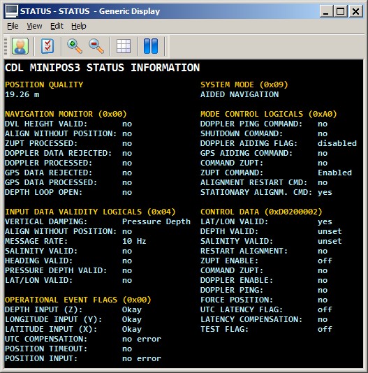
Download Generic Display Layout XML from this link as example.
(Copy the file into the current Project's \Settings\Display folder, and open it using a new Generic Display. Do not forget to select the correct system and observations ).
Furthermore, you do not need to define an extra output driver in the template setup. The driver will automatically output the USBL Position messages to the same COMport as the incoming data.
The output update rate can be selected while on-line. The information in the USBL Position message depends on the settings as selected by the user in the Setup menu. See for more information below in the Qinsy Online tab.
Online
The driver has user-interface, and therefore will always be present in the Windows taskbar. When going on-line for the first time, locate the driver and adjust the Setup parameters:
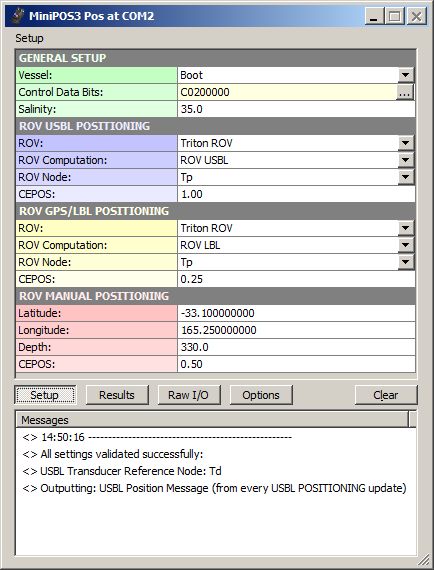
Driver Layout Menu: Setup
|
|
GENERAL SETUP |
|---|---|
|
Vessel: |
Select from the available defined objects the vessel from which the ROV will be launched. This should be the vessel that has the USBL Transducer mounted. |
|
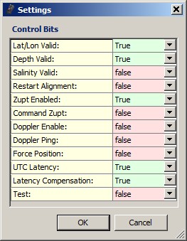
Control Data Bits: |
Use the [...] button to invoke a dialog for enabling and/or disabling the Control Data Bits.
|
|
Salinity: |
Enter the salinity in parts per thousand.
|
|
|
ROV USBL POSITIONING |
|
ROV: |
Select from the available defined objects the ROV object that is positioned by a USBL system. |
|
ROV Computation: |
Select the USBL computation and node for the ROV. This node position will be formatted and outputted as the USBL Position message , but whether it is actually used depends on the Output and Source selection in the Options menu:
|
|
ROV Node: |
Select the USBL computation and the node for the ROV. This node position will be formatted and outputted as the USBL Position message . |
|
CEPOS: |
Enter manually the Position Quality (CEPOS) for the USBL Position message . Value in meters. |
|
|
ROV GPS/LBL POSITIONING |
|
ROV: |
Select from the available defined objects the ROV object that is positioned by an LBL system |
|
ROV Computation: |
Select the LBL computation and node for the ROV. This node position will be formatted and outputted as the USBL Position message , but whether it is actually used depends on the Output and Source selection in the Options menu:
|
|
ROV Node: |
Select the LBL computation and node for the ROV. This node position will be formatted and outputted as the USBL Position message . |
|
CEPOS: |
Enter manually the Position Quality (CEPOS) for the USBL Position message . Value in meters. |
|
|
ROV MANUAL POSITIONING |
|
Latitude: |
This manual position will be formatted and outputted as the USBL Position message , but whether it is actually used depends on the Output and Source selection in the Options menu:
|
|
Longitude: |
Enter the longitude in decimal degrees. |
|
Depth: |
Enter the depth in meters. |
|
CEPOS: |
Enter manually the Position Quality (CEPOS) for the USBL Position message . Value in meters. |
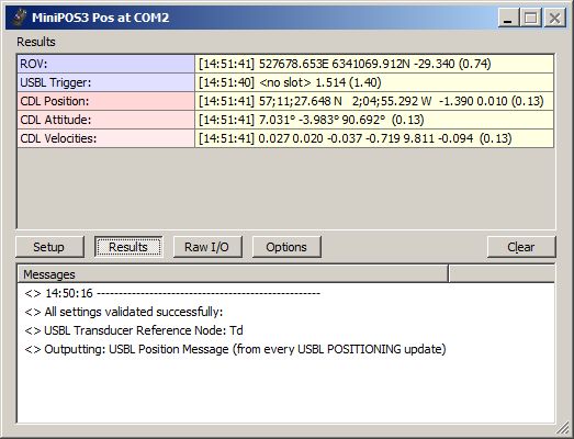
Driver Layout Menu: Results
|
ROV: |
The last encoded position for the selected ROV which will be outputted as USBL Position message . Displayed are the [Update Time], the Easting and Northing, the Height and the age of the data (between brackets) in seconds. If this age exceeds 5 seconds, then the last encoded values are displayed in the color red. |
|
USBL Trigger: |
Information about the last updated USBL Transponder. This row is only visible when the USBL Position message is outputted on USBL Trigger (see Options Menu). Displayed are the [Update Time], the Transponder Slot, the Seconds between the last two updates and the age of data (between brackets). If this age exceeds 5 seconds, then the last encoded values are displayed in red. |
|
CDL Position: |
The last decoded position data from the incoming Navigation messages . Displayed are the [Update Time], the Latitude and Longitude, Depth, Altitude and the age of the data (between brackets) in seconds.
|
|
CDL Attitude: |
The last decoded attitude data from the incoming Navigation messages . Displayed are the [Update Time], the Heading, Pitch and Roll and the age of the data (between brackets) in seconds. If this age exceeds 5 seconds, then the last decoded values are displayed in red.
|
|
CDL Velocities: |
The last decoded velocities and vehicle acceleration data from the incoming Navigation messages . Displayed are the [Update Time], the East, North and Down velocity, the vehicle X, Y and Z acceleration and the age of the data (between brackets) in seconds. If this age exceeds 5 seconds, then the last decoded values are displayed in red.
|
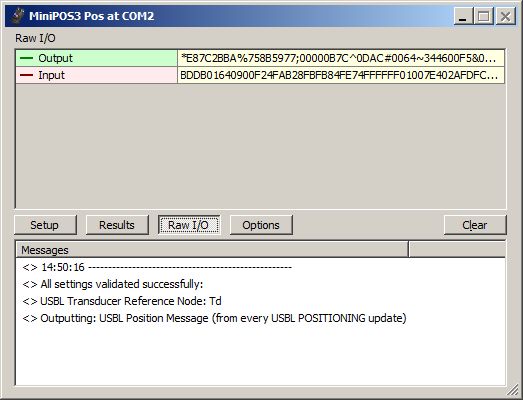
Driver Layout Menu: Raw I/O
|
Output: |
Last outputted USBL Position message to the serial COMport. The indicator cycles when a complete message has been sent. If the last output took place more than 5 seconds ago, it will be displayed in gray.
|
|
Input: |
Last received raw data at the serial COMport. The indicator cycles when a complete Navigation message is received. If no CDL MiniPOS3 data is received for more than 5 seconds, then the last received data is displayed in the color gray.
|
|
Log Raw Data: |
Enable this option only for analyzing or debugging purposes
|
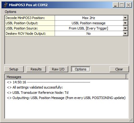
Driver Layout Menu: Options
|
Decode MiniPOS3 Position: |
Reduce the number of decoded positions from the incoming Navigation message . Useful when the CDL MiniPOS3 is broadcasting at high update rate, e.g. at 100Hz, but you don't want to store all these positions in the database. Notice that this does not affect the decoding of the attitude and velocity data, only the position message.
|
|
USBL Position Output: |
USBL Position Message will output the USBL Position message .
|
|
USBL Position Source: |
Select the source and the desired output update rate for the outputted USBL Position message .
|
|
Deskew ROV Node Output: |
Select Yes in order to skew the time and position of the ROV node to the time of output ( USBL Position message ), using the current SOG and COG. Notice that the SOG and COG depend on the Controller's Computation Setup, Object COG/SOG - Prediction Parameters Settings.
|
Dialog Buttons
|
[Setup ] |
Invoke the Setup Menu |
|
[Results ] |
Invoke the Results Menu |
|
[Raw ] |
Invoke the Raw Menu |
|
[Options ] |
Invoke the Options Menu |
|
[Clear ] |
The last 500 history messages are displayed in the message view. Use the Clear button to empty the list. |
Registry Options
Information in the Results menu will be displayed in red color when the age of the data exceeds five seconds.
-
This age limit (default 5 seconds) may be changed by modifying the registry key:
'HKEY_CURRENT_USER\Software\QPS\Qinsy\8.0\Drivers\DrvQPSTerminatedUI\<YourDriverName>\Settings\ MaxAgeRawInput'.
(Changing this age value is purely for display purposes. It has nothing to do with the actual decoding of the data)
Information in the Raw menu will be displayed in gray color when the age of the data exceeds five seconds.
-
This age limit (default 5 seconds) may be changed by modifying the registry key:
'HKEY_CURRENT_USER\Software\QPS\Qinsy\8.0\Drivers\DrvQPSTerminatedUI\<YourDriverName>\Settings\ MaxAgeRawOutput'.
(Changing this age value is purely for display purposes. It has nothing to do with the actual output of the data)
Change the following registry key (from '00' (default) to '01') if you also want to show the 'Lock Settings' and 'Show Tooltips' option in the Options menu:
-
'HKEY_CURRENT_USER\Software\QPS\Qinsy\8.0\Drivers\DrvQPSTerminatedUI\<YourDriverName>\Settings\ ShowAllOptions'
Change the following registry key (from '01' (default) to '00') if you want to hide the four dark gray separator lines in the Setup menu:
-
'HKEY_CURRENT_USER\Software\QPS\Qinsy\8.0\Drivers\DrvQPSTerminatedUI\<YourDriverName>\Settings\ ShowSetupHeaders'
Drivers IO Notes
-
PPS
The UTC Time, part of the incoming Navigation message , will be used for time-stamping the data. Only in combination with a valid PPS system. See also paragraph Timing for more information.
Notice that this command-line parameter is automatically used when you select the driver with "(UTC)" in the driver's name.
-
NOCS
This command line parameter (meaning No CheckSum) will let the driver ignore the checksum of the incoming Navigation Message . It is not recommended to use this parameter.