
Description
Bundle Results Output and Input driver combination can be used to transfer bundle shape computation results from a main Qinsy to one or more remote Qinsy's for display purposes. For example the RSV main vessel Qinsy will perform all the bundle shape calculations and the results will be sent via a radio link to the Qinsy installed on the Tugs. There the Bundle Trendometer Display will read and display these results.
The Output driver will send a bundle message every second whether the results have changed or not. The message should be considered a broadcast from the main RSV to all the Tugs. No answer is expected from the Tugs. The pace of the output is determined by the Ouput drivers' update rate.
Driver Information
|
Driver |
Bundle Results Telemetry |
Interface Type |
Serial |
Driver Class Type |
Counted |
|---|---|---|---|---|---|
|
No |
Input / Output |
Input and Output |
Executable |
DrvInputBundleResults.exe |
|
|
Related Systems |
|
||||
|
Related Pages |
|
||||
Decoding Notes
The input driver will only update when it has validated the checksum of the binary message body.
Interfacing Notes
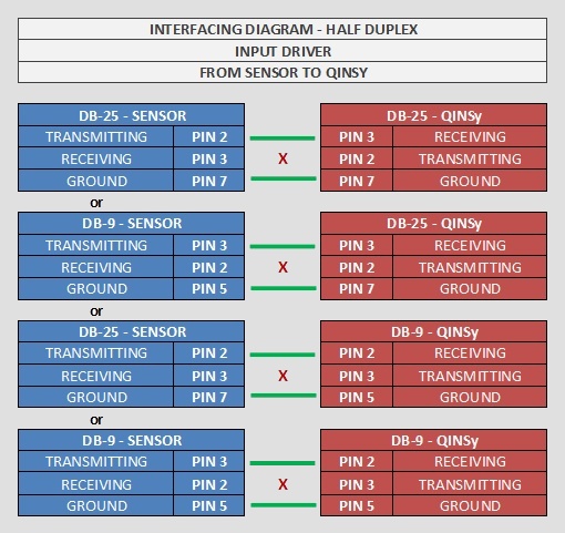
The input driver does not send any data or commands to the radio system, so only half-duplex wiring is needed.
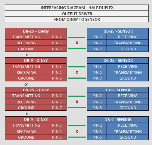
The output driver does not receive any data or commands from the radio system, so only half-duplex wiring is needed.
Database Setup
The Qinsy that calculates the bundle shape (e.g. on the RSV) should contain the Output driver.
Add a new 'Output System', select driver 'Bundle Results Telemetry Output' and select the serial port to which the radio modem is attached. Make sure output rate is set to a value that does justice to the available telemetry bandwidth; 1 second will be a typical value.
The Qinsy that is placed remotely (e.g. on the Tug) should contain the Input driver.
Add a new 'Miscellaneous System', select driver "Bundle Results Telemetry Input" and select the serial port to which the radio modem is attached. Optionally you can add some observations for debug/monitoring usage, see below.
|
Observation |
Slot |
|
Number of Transponders |
NODECOUNT |
|
Minimum (shallowest) depth of all transponders |
MINDEPTH |
|
Maximum (deepest) depth of all transponders |
MAXDEPTH |
|
Lead Tug KP (Reference KP) |
REFKP |
Note: Slot string is case-sensitive.
The Quality indicator of the number of transponders is filled with the Bundle Ref time, seconds since midnight.
This figure can be handy in debugging to see if the PositionFilter process was properly updating the data container.