
Description
Driver to decode sidescan and multibeam data from a Benthos C3D Seafloor Mapping system. The driver can optionally be used to control the Benthos System properties from Qinsy without any need for an external display or control program.
The driver requires the Benthos server application "server.exe" as an interface between the tow fish and Qinsy. The server will translate the Qinsy UDP network commands into commands for the fish and vice versa.
The driver requires the presence of the Benthos C3D server and a time server (NTP) running simultaneously on either the Qinsy PC or another PC in the network.
Info
We strongly advise to use the Qinsy SNTP Server program for the synchronization. It can be found in the Qinsy Program Files folder. Please read the article: 'How-to SNTP Server' in the Qinsy Knowledge Base.
If you use a hardware NTP server make sure its accuracy is equal to or better than 1 millisecond.
Note that the Veracity time server as advised by Benthos is not accurate enough (+/- 100 msec) and should therefore not be used!
The Benthos system can be interfaced to Qinsy in two different modes: decode only mode and decode/control mode.
In the first mode the driver will listen passively to a UDP data stream on a specific port. As long as the data is formatted according to the C3D format it will work.
Another program (e.g. Benthos display application) will be responsible for the interrogation and control of the Benthos C3D Server.
The second mode allows for sonar control from the Qinsy Controller program where Qinsy serves as the display program.
Driver Information
|
Driver |
Benthos C3D |
Interface Type |
UDP |
Driver Class Type |
|
|---|---|---|---|---|---|
|
Yes |
Input / Output |
Input |
Executable |
DrvBenthosC3D.exe |
|
|
Related Systems |
|
||||
|
Related Pages |
|
||||
Decoding Notes
The Benthos Server app. is interrogated for ping data continuously. The server replies with one or more packets (depending on the amount of transferred data) for a single ping.
It will send a ping header followed by a variable number of data blocks containing different kinds of data (e.g. angles, ranges, amplitudes, etc.).
The driver decodes the following blocks:
|
Block Nr |
Type |
|---|---|
|
50 |
RANGEDATA, Range data, Segment 0 Port |
|
51 |
RANGEDATA, Range data, Segment 0 Stbd |
|
60 |
ANGLEDATA, Angle data, Segment 0 Port |
|
61 |
ANGLEDATA, Angle data, Segment 0 Stbd |
|
70 |
AMPDATA, Amplitude data, Segment 0 Port |
|
71 |
AMPDATA, Amplitude data, Segment 0 Stbd |
|
100 |
SSDATA, 2D Sidescan data, Port |
|
101 |
SSDATA, 2D Sidescan data, Stbd |
|
253 |
STATUSDATA, free format ascii status data. (Used by control functionality of the driver to check the current fish settings.) |
Note that the driver will only decode Segment 0. If you set up the number of segments in the Benthos software as 1 then this block will contain all the beam data (water column and interpreted seafloor). If number of segments is set to 2 then this segment will contain the interpreted seafloor data.
The Status data channel is used by the driver to determine the current settings of the fish. Settings like range, sidescan output mode, gain, etc. can be decoded from this block. If Qinsy is used to control the C3D then it will force the C3D system into pinging as soon as Qinsy starts.
This is done to guarantee continuous settings feedback from the fish. For safety purposes the TX mode of the C3D is always turned off by the driver as soon as Qinsy Starts. This is to prevent damage to the transducers due to pinging in air.
The C3D can report many thousands of samples per head per ping. Every sample is converted to a beam by the driver. Note that processing this in Qinsy with a complex velocity profile may cause a strain on the system. The driver decodes for every sample the raw range data, angle data and intensity data.
The C3D reports ranges in centimeters; these are converted by the driver to one way travel time with a sound velocity value of 1500.0 m/s. Make sure that the C3D server software also uses this velocity: please check file "range.cfg" as found in the Benthos C3D program folder and make sure all sound velocity values in that file are set to 1500.
Angles are converted to degrees using the Qinsy Convention by the driver. Therefore the driver must know the Down-Look Angle of the transducers (either 20-30-40 degrees). Make sure to select the appropriate driver. Intensity data is decoded as a value between 0 and 57925 (11585 * 5).
The sample index +1 is stored as the beam number.
If PPS is used within Qinsy then the decoded time stamp will be used as the reported ping time, else the time of arrival is used. Note that the latter may be subject to network latencies.
System Configuration
The driver requires the Benthos C3D software (control panel, server etc.) to be properly installed including necessary *.dll files. This software can be obtained from Benthos or the supplier of your C3D hardware.
The application should be running at the same time as Qinsy. If server is not running then Qinsy driver will not be able to receive data or send commands to the transceiver.
It is advised to run the server application on the same computer as Qinsy to prevent any timing issues because the C3D TimeServer application will timestamp the sonar data with the system clock.
Note that the C3D software will only work with Windows XP.
Decode only mode:
The C3D ControlPanel auto start option may be enabled, choose display.exe as found in the Benthos program folder as the display application.
Decode/control mode:
The C3D ControlPanel auto start option should be disabled otherwise it will try to launch a display application. Also set up the IP addresses correctly. By default the tow fish is 192.168.0.40 and the Qinsy Computer is 192.168.0.41.
Time synchronization:
Do not start the Legacy time server but set up the C3D to use NTP Server instead. This can be from either a GPS, a dedicated NTP server or a Qinsy SNTP server (see description in Drivers help).
When using this method make sure the NTP is set up in the web interface of the C3D.
The first time that the C3D is synchronized to an NTP server, it should be allowed to run with the complete system operational for 8 hours. Before powering down, please use the Shutdown C3D button, on the main web page.
This will ensure that the NTP drift values are stored. Afterwards, if the NTP server clock is stable, the next time C3D is powered, it should reach full synchronization to the NTP server in minutes. 30 minutes should be more than enough time.
Another method is to set the time in the BIOS of the C3D computer as close as possible to UTC. In that case the synchronization should be reasonably fast.
Starting order:
-
Power up sonar transceiver.
-
Start Benthos C3D control panel. If auto start option is disabled then execute the following steps:
1) Wait until the control panel light changes from red to green.
2) Press the left start button, this will launch the server.
3) Press middle start button, this will launch the time server (optional). -
Start Qinsy
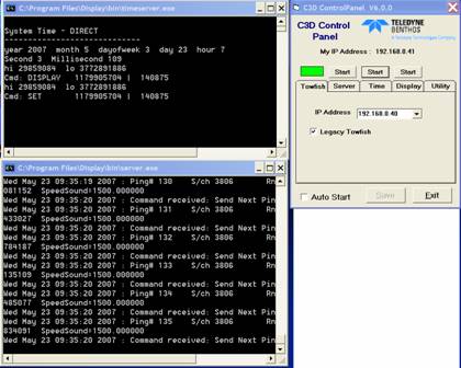
Figure: C3D control panel, server and time server.
When going on- and off-line with Qinsy it is not necessary to close the C3D control panel, server and time server. They can continue running, Qinsy will automatically connect to the server again on restart.
If communication is lost entirely and the server is not receiving any ping data from the transceiver anymore as a last resort a restart of the transceiver, C3D software and finally Qinsy may help.
For debugging, test and signal calibration purposes the C3D display application can be used. Follow the same starting order as described above but now do not start Qinsy but the display.exe app. instead as found in the Benthos C3D program folder.
Make sure that Qinsy Benthos driver and the display.exe application do not run at the same time because both of them will try to open the same TCP ports.
Interfacing Notes
The Benthos server application will listen on port 6001 for commands and it will send replies and data to port 6002, the latter being the port number to be entered in Qinsy.
Database Setup
The Benthos system can be interfaced to Qinsy in two different ways: decode only mode and decode/control mode.
This option can be set with the checkbox "Control System From Qinsy" in Database Setup-System Setup page.
Decode only mode
In this mode the driver is listening passively to a UDP data stream on a specific port. As long as the data is formatted according to the C3D format it will work. Another program (e.g. Benthos display application) will be responsible for the interrogation and control of the Benthos Server. Note that this will only work if the C3D server application broadcasts its packets (to port number 6002). Typically this means that the IP address of the display program as set up in the Benthos Control Panel should be set to something like x.x.x.255 (refer to Benthos software/manuals for more information).
Decode / Control mode
In this mode the driver interrogates the Benthos server application for ping data and will also be able to send commands (e.g. start/stop pinging, range etc.) to it. Note that only public commands are supported. In the Controller-Echosounder Settings page the settings can be modified. The Controller will relay the commands to the driver which forwards them to the C3D Server application. This app. will finally send them to the fish. The communication between Qinsy and C3D will be a bit indirect, this is caused by the fact that the C3D doesn't support any form of handshaking. Instead, if a command arrived successfully in the fish this can only be concluded by decoding the status data embedded in the ping data. The Controller will show actual settings and the status of the driver in the Echosounder settings dialog (see screen capture below).
The driver will store the last entered settings in the registry when Qinsy closes. On Restart of Qinsy the last used settings are retrieved from the registry and sent to the Benthos C3D.
Note that for safety purposes the Transmission (Tx Mode) is switched off every time Qinsy is started.
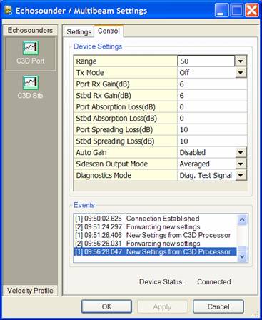
Figure: Screen capture of Controllers' Echosounder Settings dialog, driver in decode/control mode.
Database Setup
Make sure to select the driver that matches your system's Down-Look angle (20-30-40 degrees).
Single Head System: The Driver will automatically merge the beam data for both heads into the single head if it only detects one defined multibeam system for the I/O port. This is done for user convenience. Assumed is that transducers are accurately mounted in the frame since no individual calibration can be carried out and a common acoustic center is assumed for both transducers. The transducer depression angle is applied inside the driver so the entered calibration roll mounting angle should be around zero. The Node position should be defined in the middle of the transducers.
Add New Multibeam System to the template, select Driver "Benthos C3D (xx Down-Look Angle)". Set IP number to 127.0.0.1 if Benthos server.exe is running on the same PC as Qinsy. If running on another PC then the other PC's IP number should be entered. Port number will always be 6002.
Dual Head System: The driver will assign the port data to the driver "Benthos C3D (xx Down-Look Angle)" and the starboard data to the "Benthos C3D Head II (xx Down-Look Angle), note that angles should be the same for both systems".
Add two Multibeam Systems: for the first system select Driver "Benthos C3D" (port head), for the second system select "Benthos C3D Head II" (starboard head), IP number same as for single head system setup. For both drivers select the same IP address and port number 6002.
Maximum number of beams in one ping should be set to 15000 if you want to get the full number of samples on 600 meter range.
Downlook Angle/Roll Offsets: Single system: Correction is done inside the driver so the roll angle should be around zero. Dual system: if the transducers are mounted with a depression angle of 20° then the roll offsets will be typically: +70° for a port head and -70° and for the starboard head.
|
Downlook Angle |
Port Roll Offset |
Starboard Roll Offset |
|---|---|---|
|
20 |
+70° |
-70° |
|
30 |
+60° |
-60° |
|
40 |
+50° |
-50° |
If the actual depression angle of the transducers is 30 or 40 degrees then the Drivers.io file should be modified as well.
If you also want to decode sidescan data then add a Sidescan system to the template. Select Driver "Benthos C3D".
Set up same IP number and port number as the multibeam system(s).
Set sound velocity to a valid user defined value.
Add two channels: first port, second starboard, no further settings are required.
Decoding mode:
If you want to control the C3D system from Qinsy then make sure to enable the checkbox "Control system from Qinsy" on the first page of the System definition page (below Update rate).
If you want to disable the control then make sure to de-select the option for all the systems that make use of the same port number.
Online
Controller Setup
Qinsy beam reduction
A smart beam reduction algorithm is introduced to cope with the great number of samples that are reported by this sonar system. Since every sample is translated in the driver to a beam, the CPU load caused by processing beam data from an interferometric system can become rather high. If the CPU load generated by the multibeamer.exe components becomes too high then the max. beam count reduction should be enabled. Go to "Echosounder settings" dialog, for interferometric systems. The line "Max. beam count" is added to the reduction options. This works independently from the other reduction methods. Typically enable this option and select 300 here. Depending on range/sound velocity profile point count and resulting CPU load the number of kept beams may be increased or decreased.
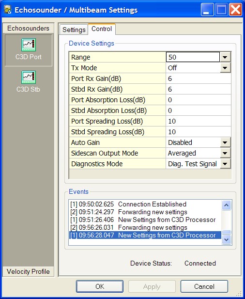
System Control
The operating settings of the sonar are modified through the Echosounder Settings dialog control Tab of the controller. The following settings can be modified:
Info
The processing and communications electronics receives, amplifies and digitizes the sonar signals and applies spreading loss and absorption loss compensation to the sonar data.
|
Settings |
Description |
|---|---|
|
Range |
Sets the time and number of samples collected between successive sonar transmit pulses. Range must be one of: 25, 50. 75, 100, 150, 200, 250, 300, 400, 500, 600 meters. |
|
Tx Mode |
Select from drop down list: Enables the selected sonar transmitter configuration. Off - Turns both the port and starboard transmitters off.
Note that for safety purposes the Transmission (Tx Mode) is switched off every time Qinsy is started. |
|
Port Rx Gain (dB) |
Sets the port receiver gain. Enter value, Min=6, Max=100dB |
|
Stbd Rx Gain (dB) |
Sets the starboard receiver gain. Enter value, Min=6, Max=100dB |
|
Port Absorption Loss |
Sets the port absorption loss coefficient for use in deriving the receive signal time varying compensation.
|
|
Stbd Absorption Loss |
Sets the starboard absorption loss coefficient for use in deriving the receive signal time varying compensation. Enter value, Min=0, Max=10dB per meter. |
|
Port Spreading Loss |
Sets the port and starboard spreading loss coefficient for use in deriving the receive signal time varying compensation.
|
|
Stbd Spreading Loss |
Sets the port and starboard spreading loss coefficient for use in deriving the receive signal time varying compensation. Enter value, Min=0, Max=100dB per Log10(range in meters). |
|
Auto Gain |
Select from drop down list:
|
|
Sidescan Output |
Sets the 2D sidescan data output mode. The outputs of each of the six receive hydrophone arrays in the port and starboard side scan sonar transducers can be enabled or disabled for viewing.
To disable all, to enable all, or to selectively enable the outputs of the receive hydrophone arrays, choose one of the following:
Generally, just enable channels 5 and 6:
|
|
Diagnostics Mode |
Sets the diagnostics mode. Mode may be:
|
Drivers IO Notes
Transducer declination angle
The transducer declination should be known by the driver to convert the angles reported by the C3D (referred to horizontal) to Qinsy angles (referred to transducer face).
By default this angle is 20 degrees but it can also be physically modified to 30 and 40 degrees. The angle can be entered in drivers.io behind the Benthos entries.
Make sure to place the same value for all the Benthos entries or else multiple driver instances will be started when Qinsy starts and decoding for either head 1, head 2 or sidescan may fail.
For correct operation only one driver executable should be started (this can be checked in the Task Manager).
Additional Information
For more information refer to Benthos website: http://www.benthos.com/.