
Description
Driver to intercept and decode the UDP/IP network communications between the PC running the ATLAS HYDROMAP CONTROL software and the ATLAS FANSWEEP 20 or ATLAS HYDROSWEEP MD2 Interface Processor. The driver decodes telegram types M-10, M-11, M-12, M-13, M-40 and M-16. The decoded data is presented to the system as TWO Multibeam systems (one per side) and a Sidescan system with two channels.
The driver will either assume that the ATLAS system is time synchronized to UTC (using hardware PPS interface) or determine the clock time difference between the Interface Processor clock and the Qinsy clock. This clock offset can be determined by time tagging the arrival of the M-40 message and deriving the transmit time that is contained in the message from it. The accuracy of this process will depend on an a low latency network link.
To improve the accuracy of the time synchronization the driver sets the timer resolution to 1 millisecond. This increases the overall scheduling speed of the Windows Operating System. The option can be disabled with a registry key (see below).
Driver Information
|
Driver |
Atlas Fansweep
|
Interface Type |
UDP |
Driver Class Type |
Network |
|---|---|---|---|---|---|
|
Yes and No |
Input / Output |
Input |
Executable |
DrvAtlasFansweep.exe |
|
|
Related Systems |
|
||||
|
Related Pages |
|
||||
Decoding Notes
The beam angles refer to the C-Keel value. They do not need any recalculation in post processing. The pitch steering angles are all zero since neither system supports pitch steering. HYDROSWEEP DS2 supports pitch steering but this can be considered the opposite of the pitch attitude value.
THE HYDROSWEEP system utilizes a receive and transmit transducer per side, totaling 4 transducers. The travel times and beam angles refer to the center of the RX (Receive) transducers.
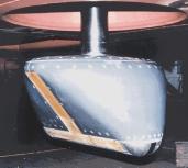

Figure: Example of an MD2 (Left) and Fansweep 20 (Right) Transducer installation.
The longitudinal axis of the RX (Receive) transducer is pointing athwarts (port-starboard direction).
All three telegrams may contain other fields that are currently not being decoded by the driver. The driver converts the two-way travel time in the type 11 telegram to one-way travel time. The driver converts the beam angle in the type 16 telegram from radians to degrees. A quality indication flag is extracted from the status field (Bit position 2 of the type 11 telegram) and placed in the least significant bit position of the beams' quality indicator. The flag is set to 1 when the beam is valid and to 0 when the beam is invalid.
The Quality indicator can be interpreted as a brightness test flag: if the beam is valid then we can consider it to have passed the brightness test.
Interfacing Notes
This driver requires an IP network connection that is capable of receiving the UDP telegrams as they are being broadcast from the ATLAS FANSWEEP 20 Interface Processor to the ATLAS HYDROMAP CONTROL system.
All three devices (Interface Processor, ATLAS HYDROMAP CONTROL workstation and the PC running Qinsy) should have IP numbers that belong to the same IP subnet.
The sounder is controlled from the HYDROMAP CONTROL program.
Database Setup
Multibeam
FANSWEEP
Add two multibeam systems, one with driver "Atlas Fansweep Port (Network Clock Sync)" and anoher with starboard.When the Fansweep system has a hardware option for PPS synchronization installed you should use the driver (With UTC)" instead. Port number should be set to 25000. On the next page set the transducer setup to "Assume Common Acoustic Center". As a node position select a position halfway between the transducers. The mounting angles can be set to zero as the HYDROMAP CONTROL already compensates for the installation angles of the transducers. Only small offsets obtained from the patch test should be entered here. Maximum number of beams should be set to 720.
The "Unit is Roll Stabilized" check box should be Selected. The Pitch and Heave Stabilization should be unselected.
HYDROSWEEP
Add two multibeam systems, one with driver Atlas Hydrosweep MD2 Port (Network Clock Sync) and another with Starboard. Note that the HYDROSWEEP system does not have hardware PPS Support. Select port number 26000. On the next page set the Transducer Setup to "Separate Transmit and Receive Elements". Fill in center of the receive element offset location for both nodes. Again leave the roll angles at zero since the coarse installation is compensated for in the Hydromap system. Maximum number of beams is 160 per system.
The "Unit is Roll Stabilized" should be Selected. The Pitch and Heave Stabilization should be unselected.
Sidescan
In order to decode the Sidescan data add a new Sidescan System, select the same driver as you selected for the multibeam, also select same the port as for the multibeam system. Add two channels, the first Port orientation, the second Starboard orientation. Choose the same transducer as for the multibeam system.
Sound Velocity
The C-keel sensor value can be decode as an extra "U/W Sensor", sound velocity observation. Simply add such a system and select the appropriate driver and same port number as above. Slot should be "Sound Velo".
Pitch Roll Heave Sensor
Due to the fact that the decoded M-13 message contains a burst of (delayed!) motion data messages, is it not suitable for use in Qinsy as a real time motion source.
Clock Offset
In order to monitor the clock offset between the ATLAS system and Qinsy you can add a miscellaneous system. Add an observation with Slot "Clock Diff". This observation will only update when the driver "Network Clock Sync" is started.
Make sure that all the systems start with the same command line argument, so either choose all with UTC option or all Network Clock Sync option. You can verify this by going Online with the Controller and checking in the Task Manager that only one process drvAtlasFansweep.exe was started.
Online
When online, select the "Echosounder settings" option from the "Settings" menu to define the online blocking and filtering of the multibeam echosounder data. Use a Raw Multibeam Display to show raw data and a Swath System Display to show the corrected scans.
Enable the "Exclude when brightness Test Failed" option in the Echosounder settings if you want to flag the invalid beam data.
Registry Options
Registrykeys can be found in:
"HKEY_CURRENT_USER\Software\QPS\Qinsy\8.0\Drivers\DrvAtlasFansweep\Settings"
Allow Time Slice Modification
Non-PPS systems only, used to increase the accuracy of the Clock Offset calculation. Sets the Windows timer resolution to 1 millisecond if set to 1 (default). In case this gives any problems set to 0, but this will affect the clock sync accuracy.
Enable Motion Logging
Optionally for debug purposes the driver can decode M-13 Motion data and drop it in a text file when this key is set to 1 (default is 0). The file is stored in the logging folder of the current Qinsy project. The files are automatically split after 10MB.