How-to Deal with ETRS89 Datum and Time-dependent Transformation Parameters
A question frequently asked by GNSS users in Europe is: How do I transform coordinates between the frames defined by ETRS89 and ITRFyy?
For users in the United States, the question is how do I transform between NAD83 and ITRFyy?
In truth, modern-day reference frame transformations have become increasingly complex to better accommodate time-dependent processes such as plate tectonics and other geophysical phenomena.
In fact, many modern frame transformations extend the classical 7-parameter Helmert transformation to complex 14-parameter formulations, which augment the original 7 parameters with their time derivatives.
This document contains:
Info: Transformation Parameter Values
Typically transformation parameter values are published; most can be found in the QPS Knowledge Base here: ITRF_Transformation_Parameters_.xlsx
ETRS, ITRS and WGS84
The European Terrestrial Reference System 89 (ETRS89) is the recommended frame of reference for geo-data for the European Union. It plays the same role for Europe as NAD83 does for North America. It uses the GRS80 as its reference ellipsoid.
The original ETRS89 reference frame was coincident with International Terrestrial Reference System (ITRS) at epoch 1989.0 and fixed to the stable part of the Eurasian Plate. It is monitored by a network of about 250 permanent GNSS tracking stations known as the EUREF Permanent Network (EPN).
Since 1989.0 the ETRS89 and the ITRS have diverged due to the northeasterly drift of the Eurasian Plate at a speed of about 2.5 cm per year. At present, the two coordinate systems differ by about 65 cm.
Since the goal is to process GNSS data in the commonly adopted ETRS89 system taking full benefit of the successively improved realizations of the ITRS, known as ITRFyy, one can derive from each annual frame determined by IERS under the label ITRFyy, a corresponding frame in ETRS89, which is labelled ETRFyy.
New WGS84 realizations (since G730, 1994) are coincident with ITRF at about 10-centimeter level. For these realizations there are no official transformation parameters. This means that one can consider that ITRF coordinates are also expressed in WGS84 at 10 cm level.
However, the most recent G1674 realization adopted ITRF2008 coordinates for more than half of the reference stations and velocities of nearby sites for the others.
Thus, ITRF2008 and WGS84 (G1674) are likely to agree at the centimeter level, yielding conventional 0-transformation parameters. For more information, check WGS84.TXT.
Info: Geodetic Information
Please refer to the Geodetic Information in the Qinsy Knowledge Base for further details about ETRS, ITRS and WGS84.
The EUREF Technical Working Group (TWG) recommends not to use the ETRF2005 and rather to adopt the ETRF2000 as a conventional frame of the ETRS89 system.
See also 'Adoption of ETRF2000' in the paragraph below.
Info: Other ETRS89 Transformations
The following explanations use the particular example where GNSS receiver measurements have been imported into a database, which are to be transformed to ETRF2000. The GNSS data had been logged as WGS84 / ITRF2008 coordinates on 1 July 2014.
The same principles would still apply when transforming between other alternative ITRF and ETRF realizations.
Info: Transformation Results
The European Plate drifts north-east with respect to the ITRS and WGS84. Therefore, geographic positions on WGS84 east of longitude 0° will have a smaller latitude North and a smaller longitude East if transformed to ETRS89.
Points west of longitude 0° will get a smaller latitude North and a larger longitude West.
Time-dependent Datum Transformation Parameters
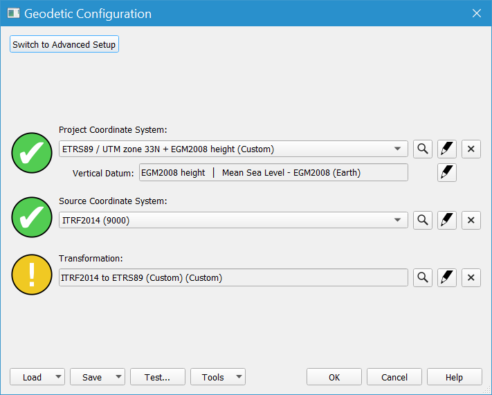
Datum transformation parameters encountered on the Geodetic Configuration Overview are needed to transform time-dependent position coordinates between two datum ellipsoids.
It is possible to enter these parameters after defining the Project CRS and the Input CRS.
Usually the 'Input' datum is ITRFyy, and the 'Projected' CRS is the local survey datum.
In this example the datums are ITRF2014 and ETRS89.
Geodetic Configuration - Guided Setup

Geodetic Configuration - Transformation
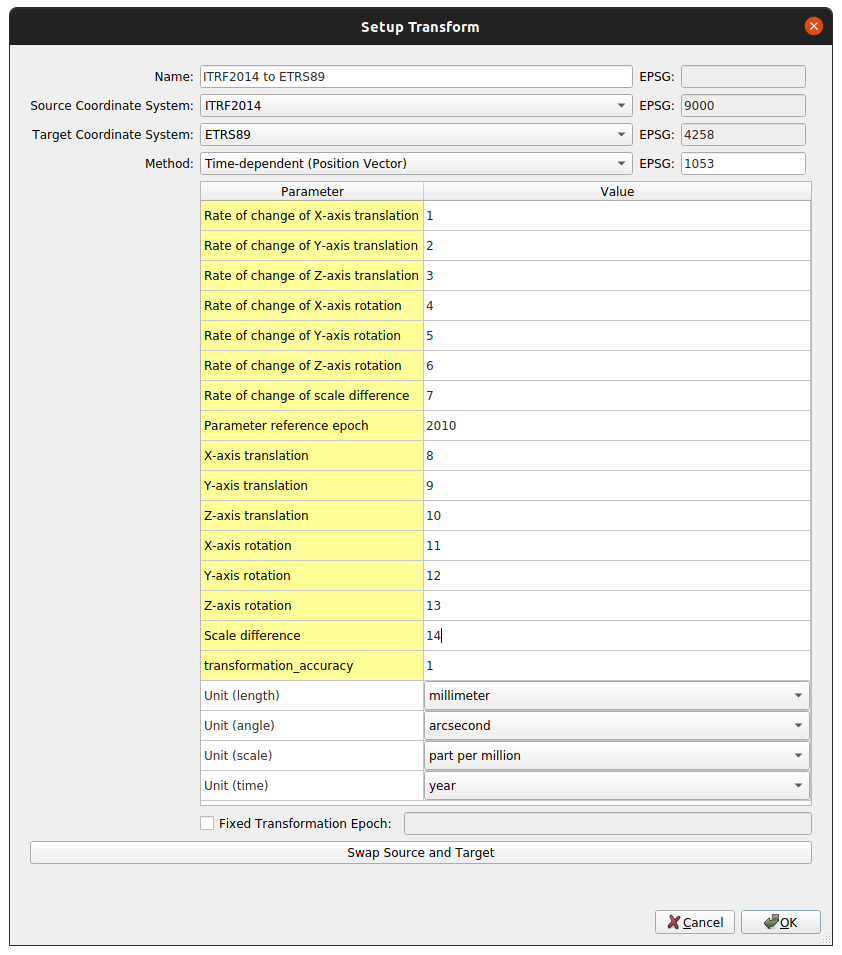
In case a Time-dependent Helmert Transformation is selected, the Transformation page at the Geodetic Configuration requires entry of the Fixed Parameters as well as the Parameter reference epoch t0 of the datum transformation.
t0 is entered as decimal years.

This window is divided into various parts:
| Setup Transform | |
|---|---|
| Name | Name of the transformation, automatically filled by the dialog. It is possible to change this name to a custom name. |
| Source Coordinate System | Input Datum. In this example the datum transformation is from ITRF2014 (Source CRS) to local datum ETRS89 (Epoch 2010.0). NOTE: The current ITRF realization ITRF2014 (Epoch 2010.0). Typically the GNSS positioning data output is referenced to this realization. See also 'Reference Frames - Differential Corrections' in the paragraph below. |
| Target Coordinate System | Local Survey datum. In this example the datum transformation is from ITRF2014 to local datum ETRS89 (Target CRS). |
| Method | Options are:
There are two possible rotation modes: Position Vector Rotation and Coordinate Frame Rotation. In this example, Time-dependent (Position Vector) |
| Rate-of-change | Enter the rate-of-change parameters for t0 (in units per year). The rate that the Shift parameters dX, dY and dZ change per year, i.e. how quickly the origins of the two datum ellipsoids move apart or together. NOTE: Be aware that time-dependent parameter values are often given in millimeters (mm) and milliarcseconds (mas). |
| Parameter reference epoch | The reference epoch t0 must be defined when a Time-dependent Transformation has been selected. In this example, 2010.0. |
| Parameters | Shift parameters dX, dY and dZ define the translation (shift) between the origins (coordinate axes) of the two datum ellipsoids. In this example, enter the Shift, Rotation and Scale Correction values needed to transform ITRF2014 to ETRS89. See below for an explanation of the derivation of these numbers. NOTE: Be aware that published time-dependent parameter values are often given in millimeters (mm) and milliarcseconds (mas). |
| Unit (length) | Select between meter, millimeters, US Survey Foot, Foot or Fathom In this example, millimeters. |
| Unit (angle) | Select between degrees, arcseconds (1/3600 degrees), milliarcseconds, radiants, microradians (10-6 radians), or grads. In this example, arcseconds. |
| Unit (scale) | Select between part per million, part per billion, and unity. In this example, Part per Million. |
| Unit (time) | By default set to year. |
| Fixed Transformation Epoch | The transformation epoch t is the time which is to be used for the actual datum transformation computations, in decimal year format, for a time-dependent datum transformation. Note: A dynamic epoch is used in most cases, since for a transformation from a fixed global datum to a moving continental datum, you would want to apply the full shift due to plate tectonics up to the date of survey. A fixed transformation epoch would only be used in case of test points (for a specific date), if a GNSS receiver outputs positions on the continental datum for a specific date, or if you specifically require the use a specific date. In case this epoch is dynamic, Qinsy (in online mode) will use the middle of the current day (12:00 UTC) to compute new dynamic datum transformation parameters. In this example nothing is defined, so a dynamic epoch will be used. |
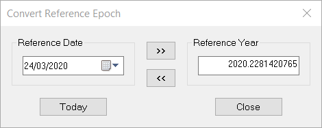
Database Setup - Convert Reference Epoch
A decimal year value can be converted from a calendar date using the 'Convert Reference Epoch' option in the Database Setup program.

Source of Transformation Parameter Values
These sources of transformation parameter values are both found in the Qinsy Knowledge Base (also available on the Internet).
QPS ETRS89 Transformation Parameters Spreadsheet
Transformations between ETRS89 realizations and ITRF are given in ITRF_Transformation_Parameters_.xlsx (ETRS89 worksheet). In this example the numbers came from worksheet ETRS89, row ITRS2008 to ETRF2000.
Info: 14-Parameter Transformation
Time-dependent transformations in Qinsy use this single-step 14-parameter transformation procedure rather than the two-step described in the EUREF Technical Working Group (TWG) memo.
If you only have access to parameter values for ITRFyy-to-ITRFxx and parameter values for ITRFyy-to-ETRFxx, you will have to compute the 14 parameters for a direct transformation ITRFyy-to-ETRFxx as presented below.
Memo from the EUREF Technical Working Group (TWG)
The EUREF Technical Working Group (TWG) recommends not to use the ETRF2005 and rather to adopt the ETRF2000 as a conventional frame of the ETRS89 system. See the Memo of Boucher and Altamimi (first issued in 2001 and updated since then at each ITRF release) for more details.
Table 5 in the Memo lists the 14 parameters to be used when transforming directly from ITRFyy into ETRF2000. In the example this was from IRTF2008 into ETRF2000.
Alternatively, the transformation of IRTF2008 into ETRF2000 can be a two-step procedure as shown in the table below.
- ITRF2008-to-ITRF2000 using the IERS published values which could be derived from Table 1 and 2 of this memo. Note that Table 5 has been compiled using the more recent and accurate values for the ITRFyy-to-ITRFyy transformations that can be found in Transfo-ITRF2008_ITRFs.txt.
- ITRF2000-to-ETRF2000 consists of the translation (shift) parameter values which are taken from Table 3 of this memo (use Case A) and the rotation rate values from Table 4. The rotation values at epoch 2000.0 are computed by multiplying the rotation rates by 11, i.e. (2000.0 - 1989.0).
Parameter | Unit | ITRF2008 | ITRF2000 | 1989.0 to 2000.0 | ITRF2000 | ITRF2008 |
|---|---|---|---|---|---|---|
| Epoch | YYYY.y | 2000.0 | 1989.0 | 2000.0 | 2000.0 | |
| T1 (X Shift dX) | m | -0.0019 | 0.0540 | 0.0 * 11 | 0.0540 | 0.0521 |
| T2 (Y Shift dY) | m | -0.0017 | 0.0510 | 0.0 * 11 | 0.0510 | 0.0493 |
| T3 (Z Shift dZ) | m | -0.0105 | -0.0480 | 0.0 * 11 | -0.0480 | -0.0585 |
| D (Scale Correction) | ppm | 0.00134 | 0.0 | 0.0 * 11 | 0.00000 | 0.00134 |
| R1 (X Rotation Rx) | " | 0.000000 | 0.0 | 0.000810 * 11 | 0.000891 | 0.000891 |
| R2 (Y Rotation Ry) | " | 0.000000 | 0.0 | 0.000490 * 11 | 0.005390 | 0.005390 |
| R3 (Z Rotation Rz) | " | 0.000000 | 0.0 | -0.000792 * 11 | -0.008712 | -0.008712 |
| dT1 (Rate X Shift dX) | m / y | 0.0001 | 0.0 | 0.0 | 0.00000 | 0.0001 |
| dT2 (Rate Y Shift dY) | m / y | 0.0001 | 0.0 | 0.0 | 0.00000 | 0.0001 |
| dT3 (Rate Z Shift dZ) | m / y | -0.0018 | 0.0 | 0.0 | 0.00000 | -0.0018 |
| dD (Rate Scale Corr.) | ppm / y | 0.00008 | 0.0 | 0.0 | 0.00000 | 0.00008 |
| dR1 (X Rotation Rx) | " / y | 0.000000 | 0.000081 | 0.0 | 0.000081 | 0.000081 |
| dR2 (Y Rotation Ry) | " / y | 0.000000 | 0.000490 | 0.0 | 0.000490 | 0.000490 |
| dR3 (Z Rotation Rz) | " / y | 0.000000 | -0.000792 | 0.0 | -0.000792 | -0.000792 |
Adoption of ETRF2000
In order to harmonize future realizations of the ETRS89 overall Europe, the EUREF Technical Working Group (TWG) recommends not to use the ETRF2005 and rather to adopt the ETRF2000 as a conventional frame of the ETRS89 system.
This decision was taken by the TWG, noticing that coordinate shifts at epochs posterior to 1989.0 occur between ETRFyy frames which are originally due to equivalent shifts between the global ITRF frames.
Therefore the adoption of the ETRF2000 as a conventional frame of the ETRS89 realization will minimize the coordinate shifts at epochs posterior to 1989.0 between different implementations of the ETRS89 in different European countries.
Consequently, the European countries who will adopt the ETRS89 or want to redefine their national systems are encouraged to adopt the ETRF2000 frame and to express their station coordinates in that frame.
These shifts are due, mainly, to the Z-translation rate of 1.8 mm/year between ITRF2000 and ITRF2005 as well as to the refined rotation rate values ( _RY Y ) listed in Table 4.
Therefore the adoption of the ETRF2000 as a conventional frame of the ETRS89 realization will minimize the coordinate shifts at epochs posterior to 1989.0 between different implementations of the ETRS89 in different European countries.
Consequently, the European countries who will adopt the ETRS89 or want to redefine their national systems are encouraged to adopt the ETRF2000 frame and to express their station coordinates in that frame.
Moreover, in order to benefit from the ITRF2005 solution, the TWG has also recommended that all European stations coordinates (GNSS, VLBI, SLR and DORIS) which are available in the ITRF2005 to be expressed in the ETRF2000 frame and to call the resulting set of coordinates (positions and velocities) ETRF2000(R05).
Similarly, the European station coordinates available in ITRF2008 solution (Altamimi et al., 2011) were also expressed in ETRF2000 and the corresponding list is called ETRF2000(R08). These two lists are available at http://etrs89.ensg.ign.fr.
It should be noted that this general two-step (or 14 parameter transformation) procedure could be applied to any other ETRFyy instead of ETRF2000.
For instance, if a country has adopted ETRF93 and for legal reasons wants to stick to that frame, then their GNSS station coordinates expressed in recent ITRF version (say ITRF2005) should first be transformed in ITRF93 and subsequently transformed in ETRF93 using the formula of the Memo.
Reference Frames - Differential Corrections
GNSS positions are defined in terms of earth centered, earth fixed Cartesian coordinates, X, Y and Z. Typically, they are converted into the latitude, longitude and height system, sometimes referred to as a geographic coordinate system.
Coordinate systems are based on mathematical models of the earth called datums that can be defined globally or for specific regions. Over time the models are updated as continents shift and the earth’s surface changes, and hence many revisions of a single datum can exist.
Differential corrections are generated against a known coordinate, referred to as the reference position. It is important to understand that for the exact same physical location, many reference positions can exist, depending on how the coordinate system was defined.
For example, EUREF in Europe publishes reference positions for each reference station in terms of both the ITRF2008 datum and the ETRF2000 datum.
When using differential corrections, an important issue to bear in mind is that GNSS positions generated from differential corrections will be in terms of the datum used for the reference position.
If GNSS positions are to be used in the context of GIS data referenced in a different frame, the positions must be transformed to that new reference frame.
If this is not done, an offset (often referred to as a datum shift or bias) is observed between the GNSS position and the background GIS data. This can be a difference of meters.
Mixing Reference Frames
Differential correction sources use a variety of reference frames. Autonomous GNSS positions use the WGS84 (World Geodetic System) datum as the reference frame.
WAAS corrections use ITRF2000 (International Terrestrial Reference Frame), US Coast Guard beacons use the NAD83 (2011), and OmniSTAR uses NAD83 in North America and WGS84 in all other world areas.
Post-processed GNSS positions are in terms of the base provider’s reference position.
This variety of reference frames means mixing autonomous, real-time, and post-processed positions can lead to inconsistency in your data.
Merging data from different reference frames requires vigilance, otherwise you may be unknowingly comparing data from one coordinate system with data from another.
The best safeguard against introducing datum shift errors into your data is to post-process all data—including real-time corrected data—against a base provider with a reference position in a known datum. All post processed positions will be in this known datum.
After post-processing, carefully apply the appropriate datum transformation between your GNSS data and your GIS.
