
In laying operations many vessels may be involved. These are sometimes linked by telemetry.
Separate notes are already available on this, see our other Knowledge Base document "How-to Anchor Handling".
On this page:
Database setup
For a pipelay operation a few objects and systems are required in the setup:
|
Entry |
Object / System |
|---|---|
|
Barge |
Object |
|
Touch Down Point |
Object |
|
Heading sensor (on the barge) |
Gyro System |
|
Positioning System (on the barge) |
Positioning System |
|
Layback System |
USBL System |
|
Pipe Lay Administration |
P5 / 94 Generator System |
Of course additional systems can be added to the database like multibeam systems, motion sensors, additional objects like tugs etc.
Touch Down Point Calculation
It depends on the selected USBL driver in the Database Setup how the Touch Down Point will be calculated.
However, it is important to get the best estimation possible, as this dynamically changes the bargetrack. Normal working practice would have an ROV for monitoring or other checks available to confirm the results.
See the Drivers Manual for a description on the various layback options.
More information on layback can be found in the "How-to Layback" document in the Knowledge Base.
Online
Pipe/Cable Lay
During a pipelay operation it is important that the Touch Down point follows the designed route as it is the goal of the complete operation to position the pipe on top of this designed route.
To achieve this, the barge needs to follow a slightly different route, the so called Bargettrack.
The Bargetrack is a projection of the mainline based on the layback of the Touch Down point or any other towed object.
As well as displaying a dotted path to follow, the software calculates the required heading to follow along the track.
This is equal to the tangent of the curve at the touch down point.
The conditions to make the bargetrack calculation work are:
-
The mainline must be a Route containing theoretical radii and not a series of lines
-
The steered node must be the Touch Down Point (TP) which needs to be set in the Controller's Computation Setup
-
A USBL system needs to be present in Database Setup
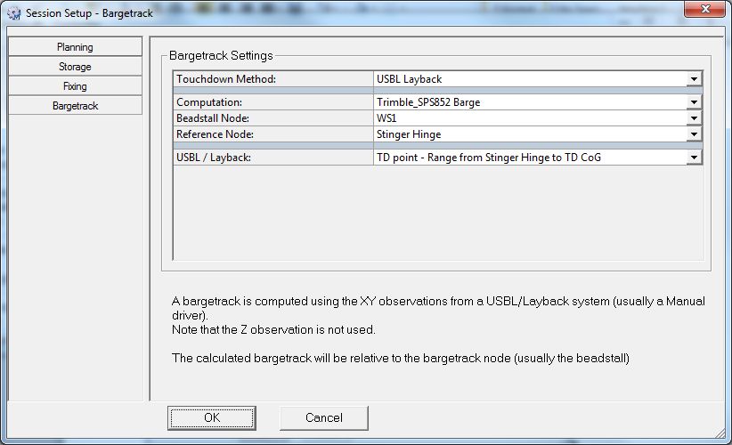
To enable the bargetrack option, check the option Cable/Pipe Lay in the Controller (Settings - Session Setup):
Displays
The bargetrack can be made visible in various displays.
Navigation Display
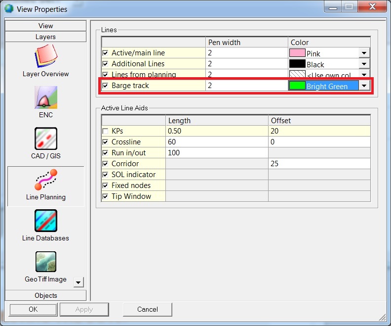
To make the bargetrack visible in the Navigation Display it needs to be activated in the properties of the display:
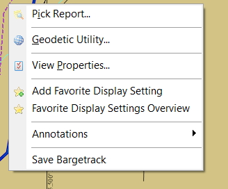
Note that the bargetrack can be saved from the Navigation Display by right clicking on the bargetrack and selecting the option Save Bargetrack:
Generic Display
Use the Generic Display Manager to select which items to show in the Generic Display:

Helmsman Display
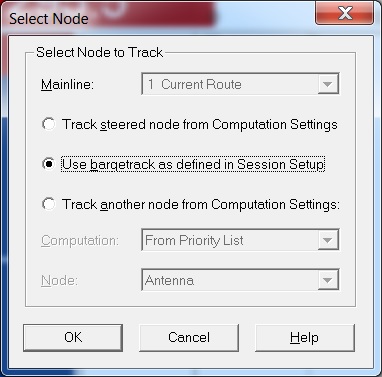
The offsets shown in the Helmsman Display are by default relative to the mainline.
This can be changed in the Select Node dialog (Select Menu):
Pipe Lay Administration
The Pipe Lay Administration can be used to log pipe lay specific data into a text file.
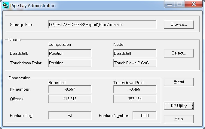
The Pipe Lay Administration dialog will show up online when this system is added to the template database.
Select computations and the correct nodes representing the Beadstall and the Touchdown point.
When 'Event' is clicked on a dialog will open to enter information on the event to log. (Feature text and a feature number. e.g. Field Joint numbers.)
After clicking OK, all information visible in the Pipe Lay Administration will be written to the text file.
Glossary of Pipe-Laying Terms
|
Anode |
Soft metal fitted at regular intervals to cathodically protect pipe from decay. |
|
B/S Beadstall |
First welding station on a lay barge. Normally the main reference point. |
|
Counter Weight / Counteracts |
Large weight placed on the inside of curves to hold the pipe. |
|
CP Survey |
Cathodic Protection Survey. |
|
Cut to length |
Calculation done to decide final length of pipe to build before a lay-down. |
|
DMA |
Dead Man Anchor.
|
|
Dope station |
Area where field joints are coated in bitumen. |
|
FJ |
Field Joint
|
|
Flop / Forwards |
The Flop Forward point is the point where the pipeline or cable would end if it were lowered from the barge and were placed flat on the sea floor.
|
|
FOF |
Face Off Flange.
|
|
Layback |
Distance from reference point to touch down. |
|
Mattress |
Where two pipelines cross over each other, the pipeline crossing has to be protected.
|
|
MIF |
Mattress Installation Frame.
|
|
Mill Count |
Calculation of length based on factory provided lengths of each joint. |
|
Overbend |
First curve as the pipe leaves the stinger. |
|
PHI |
Departure angle at stinger. |
|
Pig Launcher / Catcher |
Large unit at the end of pipe which contains Pigs which are pushed through the pipe pneumatically to clean or test them. |
|
Pin Pile |
Method of starting a lay using a pile instead of an anchor. |
|
PLEM |
Pipe Line End Manifold.
|
|
Pull |
Forward movement of the barge for one or two joints (Double jointing). |
|
Pup |
Short piece of un-coated pipe. |
|
Sagbend |
Last curve as the pipe touches the seabed. |
|
Sleepers |
Areas of rock that act like railway sleepers for the pipe. |
|
Snake Lay |
Pipe route with regular curves to cope with later expansion. |
|
Spool piece |
Section of pipe made to measure to connect up pipes. |
|
Stinger |
Supporting frame for the pipe hinged onto the stern of the vessel. |
|
Tee Piece |
T junction / connection in pipe, could be a hot tap. |
|
TP Touch down Point |
Point at which the pipe no longer moves on the seabed (Hard).
|
|
UT |
Ultrasonic Testing.
|