How-to Tow Fish or ROV
This document describes how to deal with a Tow fish or an ROV within a Qinsy project.
First we will describe how to set up the Database Setup.
Then we will describe all the items which have to be taken into account when working Online.
Info
In this document the Tow Fish is used as an example. Setting up an ROV works exactly the same.
The only thing that is different is that in the Database Setup as Type "ROV, AUV, Towhead" is chosen instead of 'Towed Fish'.
On this page:
Database Setup
In the Database Setup Program a separate Object for the Towed Fish needs to be defined.
Also a new System needs to be defined to position the Towed Fish.
Define new Object
- In the Database Setup program right click on Object and select New Object.
- Select Towed Fish as Type.
- Enter a Name.
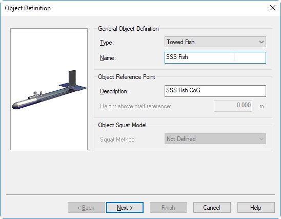
- Click on Next.
- Define the dimensions of your Towed Fish in the same way you did for your vessel.
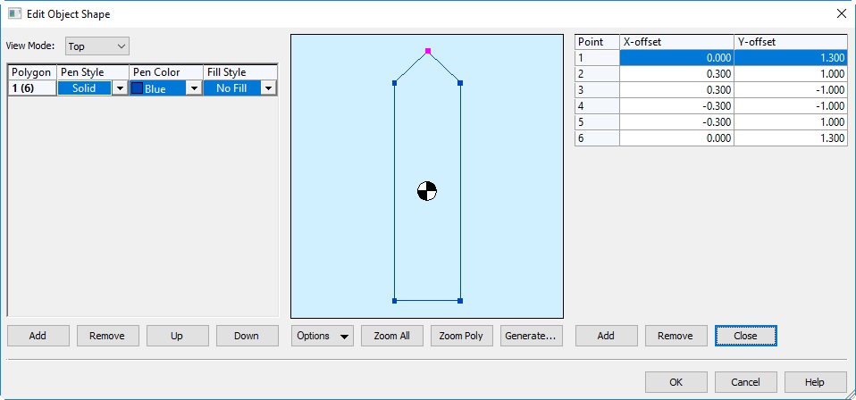
- Click on OK and then Finish.
Define new System
Different systems can be used to position the tow fish:
- Right click on Object and select New System.
- Enter a Name for your system.
Layback System (Manual Layback or Cable counter) in combination with depthsensor.
- Select Layback System as Type.
- Select Manual Layback as your Driver or, in case you use a cable counter, select the appropriate cable counter driver.
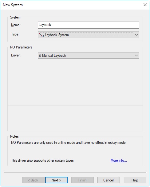
- Press Next.
- Select your vessel as the Object on which the layback system is installed.

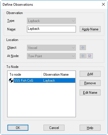
- Click on Add to add an Observation.
- Select Layback as Type.
- Select the Tow point on the vessel as At Node.
- For the To Node click on Add to select the Connection point on your Towed fish.
(For a small fish, you can select the CoG of the fish. For bigger fish, you can define a node on the fish which represents the actual connection point.) - Enter an Observation Name (e.g. Layback) and press OK.
- Click on OK.
- Click on Next.
- Define your A-priori SD and if necessary C-O values and a Scale factor:
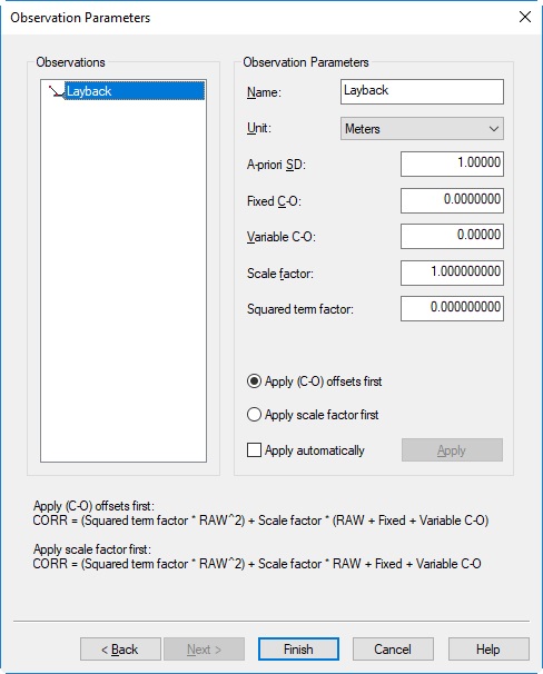
- If you have entered any values, click on Apply Properties to Observation.
- Click on Finish.
- Click on Cancel when you get the message whether you want to Add a Related System.
- Save your new Template Database and Close the Database Setup Program.
Read more
More information about the Manual Layback driver can be found in the Knowledge Base document named 'How-to Layback'.
Output represents Range
When you are using a cable counter, make sure that the output represents the range. If necessary use a C-O value and/or scale factor.
Depth Sensor
An extra system needs to be defined for the depth indication of the fish.
- Right click on Object and select New System.
- Enter a Name for your system.
- Select Underwater Sensor as Type for your system.
- Select # Manual Underwater Sensor Input as Driver if the depth will be entered Online manually.
Choose one of the other drivers in case you have a depth sensor on the Tow fish or if the SSS measures depths.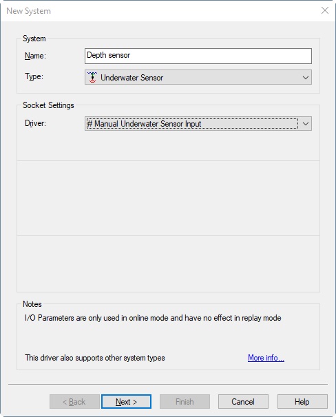
- Click on Next.
- Select your Tow Fish as Object.
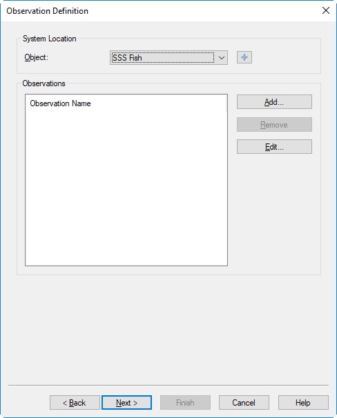
- Click on Add to add an Observation.
- Select ROV Depth as Type.
- Select as At Node the CoG of your Tow Fish or the node with the exact position of the depth sensor on the Tow Fish.
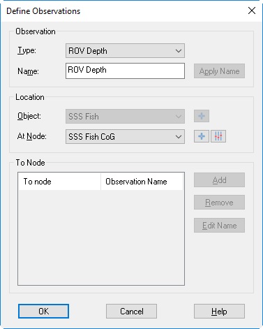
- Click on OK.
- Click on Next.
- Define your A-priori SD and if necessary C-O values and a Scale factor.

- If you have entered any values, click on Apply Properties to Observation.
- Click on Finish.
- Click on Cancel when you get the message whether you want to Add a Related System.
- Save your new Template Database and Close the Database Setup Program.
USBL System
- Select USBL System as Type for your system.
- Select the appropriate Driver for your USBL sytem and enter the I/O Parameters.
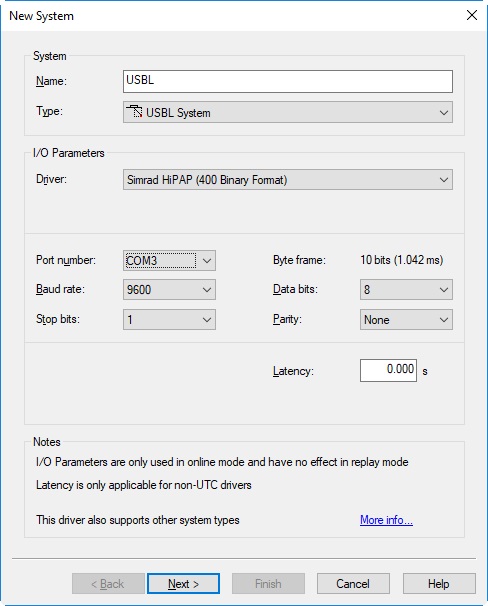
- Click on Next.
- Select your vessel as Object.
- Select the Transducer node of the USBL at Transducer.
- Select the node for which the USBL measurements are valid as Reference Node.
- Make sure the rest of the settings are correct. For more information use the F1 Inline Help.
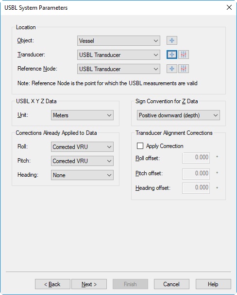
- Click on Next.
- Enter the Used sound velocity. This is the sound velocity that is entered in the USBL system itself.
- Enter the Calibrated sound velocity. This is the sound velocity as measured with the sound velocity probe.
- Make sure the rest of the Parameters are correct. For more information read the F1 Inline Help.
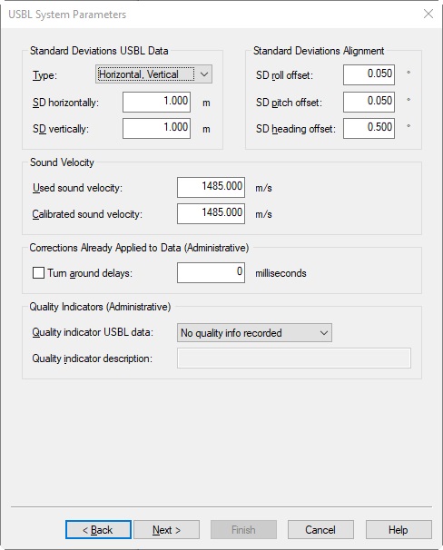
- Click on Next.
- Click on Add to select a USBL target.
- Select the Node for your USBL transponder or click on Add again to create one.
(For a small fish, you could select the CoG of the fish.)
- Click on OK.
- Click on Edit to enter the slot number of the transponder.
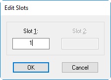
- Click on OK.
- Click on Finish.
- Save your new Template Database and Close the Database Setup Program.
USBL with Depth Sensor
It is also possible to use a USBL system in combination with a Depth Sensor.
Create your depth sensor in exactly the same way as with thelayback system with depthsensor.
Online
Fill in the following dialogs while online:
- Go Online with your created Template Database.
Computation Setup
- Select Computation Setup from the Settings Menu in the Controller.
- Tick the boxes to enable your Layback System or your USBL System.
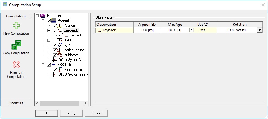
Example of Layback System in combination with Depth Sensor.
Or: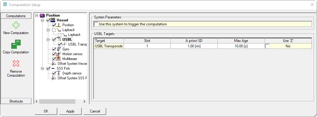
Example of USBL System. - In case no depth sensor is used tick the option Use 'Z' for the Layback or the USBL system.
The Z value of the layback system or the USBL system will be used to calculate the height. - If a depth sensor needs to be used to calculate the height, disable the option Use 'Z' for the USBL system or the Layback system and select the Depth Sensor system in the computation tree.
- Click On OK.
Use the Node QC Display
Use the Node QC Display to check if your computation is working correctly.
Choose one of the nodes on your Tow Fish or ROV.
More information about the Node QC Display can be found in the F1 Inline Help.
Position Filter
In case the USBL gives noisy data that results in a track that is noisy then a Position filter can be used on the Tow Fish object.
- Select the fish in the computation setup and select the Position Filter tab.
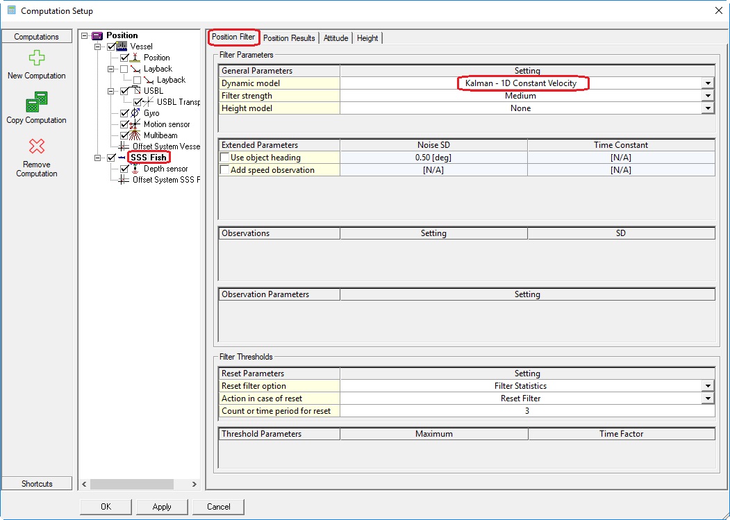
- From the Dynamic model drop down menu a suitable model can be selected.
The Controller has extensive F1 Inline help on this function so refer to this help to choose a model. - Tune the performance of the filter.
The main tuning is done by changing the A-Priori SD of the USBL.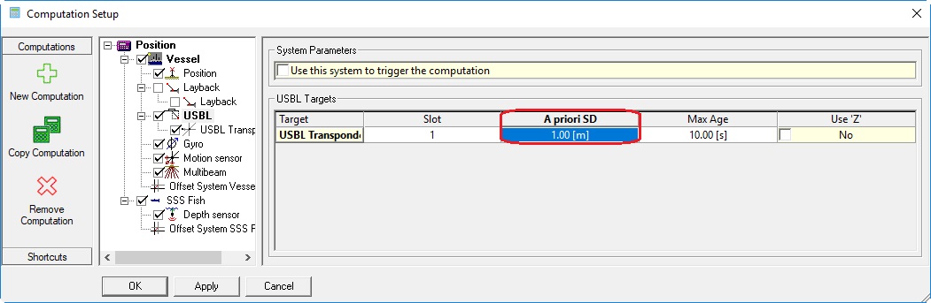
Manual Input Drivers
In case you are using Manual Input drivers for your Layback system or Depth sensor you need to enter the correct values and make sure that the observation is updating.
- Enter the correct Value in the Manual Input driver:
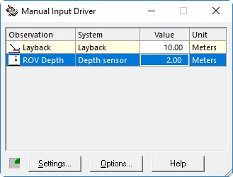
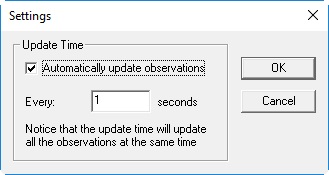
- Click on Settings at the Manual Input Driver and make sure the Layback observation is updating:
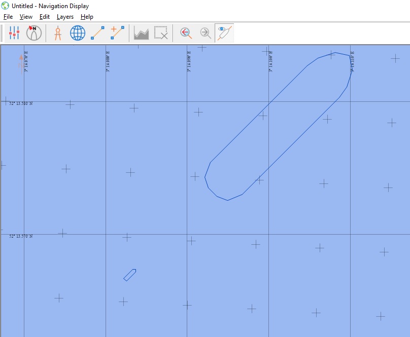
Navigation Display
In the Navigation Display you can see your Vessel shape and your Towed Fish: