
How-to Total Propagated Uncertainty - TPU
This document describes some of the theory behind the so-called Total Propagated Uncertainty (TPU) as well as the settings needed to compute and display the TPU values for echosounder footprint points in Qinsy.
On this page:
Understand and use the Total Propagated Uncertainty (TPU)
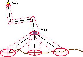
The Total Propagated Uncertainty (TPU) of a point is a measure for the accuracy to be expected for such a point, when all relevant error / uncertainty sources are taken into account. Instead of “TPU”, the term “error budget” is also used or "TPU" (Total Propagated Uncertainty). The TPU for a DTM point on the sea floor that is computed from an echosounder measurement, consists of the TPU of the echosounder system transducer position plus the contribution of the relative depth sounding.
Uncertainty sources that are to be considered are (GPS) position, draft, squat, load, tide (including spatial/temporal prediction to the depth measurement position), geoid model, bathy depth, node offsets, timing offsets, SOG (Speed Over Ground) and CMG (Course Made Good), gyro heading, pitch, roll and heave, mounting offsets, beam range, beam angle, beam width, beam steering, sound velocity at transducer head, sound velocity profile. Hence the indication “Total”.
All measurements are considered to be uncorrelated random variables with normally distributed uncertainties, all uncertainty sources acting independently, so all covariance terms can be disregarded, and the TPU can be computed statistically using the well-known Law of Uncertainty Propagation. Hence the indication “Propagated”.
The TPU value thus results from the combination of all contributing uncertainties. Hence the indication “Uncertainty”.
In most echosounder error budget analysis studies and hydrographical survey standards, such as IHO S-44, separate TPU’s (or error budgets) for horizontal position (georeferencing) and vertical depth (soundings) are considered. The accuracy of a position is the accuracy of the position of a feature (e.g. sounding, navigation aid) to be located within a geodetic reference frame. Depth accuracy is to be understood as the accuracy of the reduced depths. Typically, sounding accuracy criteria are 10 times as strict as georeferencing criteria.
In QINSy, as in IHO S-44, accuracy values are always presented as 95% confidence level values. However, a priori standard deviations for uncertainty sources are always to be entered as 1 sigma values (68% confidence level).
Total Propagated Uncertainty of DTM Points
IHO Standards for Hydrographical Surveys, S-44, Edition 6.0.0, 2020
The International Hydrographic Organisation (IHO) has issued standards for hydrographic surveys (S-44) since 1957, and most recently in 2020 [1]. These are the standards used by most producers of hydrographic data, for example the Hydrographic Department of the Royal Netherlands Navy.
Their stated purpose is "to provide a set of standards for hydrographic surveys primarily used to compile navigational charts essential for the safety of navigation, knowledge and the protection of the marine environment”.
S-44 Edition 6.0.0 classifies surveys into five different types:
Exclusive Order
For shallow water areas where there is an exceptional and optimal use of the water column and where specific critical areas with minimum underkeel clearance and bottom characteristics are potentially hazardous to vessels.
Special Order
For areas where underkeel clearance is critical.
Order 1a
For areas where features on the bottom may become a concern for the type of surface traffic expected to transit the area but where the underkeel clearance is considered not to be critical.
Order 1b
For areas where the types of surface vessels expected to transit the area is such that a general depiction of the bottom is considered adequate.
Order 2
For areas where the depth of water is such that a general depiction of the bottom is considered adequate.
S-44 Edition 6.0.0 specifies for each of these orders of survey, horizontal accuracy (95% confidence level), depth accuracy (95% confidence level), bathymetric coverage requirement and feature detection capability. It divides depth uncertainties into two contributing types: constant and variable (depth-dependent) uncertainties. The two types are combined in the Root-Sum-of-Squares sense to give the 95% uncertainty, s=√(a 2+(b*d) 2), with: a=sum of all depth-independent uncertainties, b=sum of all depth-dependent uncertainties, expressed as a fraction of water depth, and d=depth of water column in metres.
The accuracy of a position is the accuracy at the position of a feature (e.g. sounding, navaid) to be located within a geodetic reference frame. The positions of soundings, dangers and all other significant submerged features should be determined such that the horizontal uncertainty (THU) is as specified in Table 1. The horizontal positions of navigation aids and other important features should be determined to the uncertainty stated in Table 2, at 95% confidence level.
Vertical uncertainty (TVU) is to be understood as the uncertainty of the reduced depths. All relevant uncertainty sources should be combined to obtain a Total Propagated Uncertainty (TPU). The allowable vertical uncertainties are computed by using for a and b the values from Table 1 in formula s=√(a 2+(b*d) 2).
Contrary to earlier editions of S-44, Edition 6.0.0 does not have strict depth limits for choosing the order to be applied, except that it recommends using Order 2 in areas which are deeper than 200 metres.
| Order | Exclusive | Special | Order 1a | Order 1b | Order 2 |
|---|---|---|---|---|---|
| THU Limit (95% Conf. Level) | 1 m | 2 m | 5 m + 5% depth | 5 m + 5% depth | 20 m + 10% depth |
| TVU Limit (95% Conf. Level) | a = 0.15 m b = 0.0075 | a = 0.25 m b = 0.0075 | a = 0.5 m | a = 0.5 m | a = 1.0 m |
| Bathymetric Coverage | 200% | 100% | ≤ 100% | 5% | 5% |
| Feature Detection | cubic features > 0.5 m | cubic features > 1 m | cubic features > 2 m in depths down to 40 m; 10% of depth beyond 40 m | not specified | not specified |
Table 1. IHO S-44, Edition 6.0.0. Summary of Minimum Standards for Hydrographic Surveys
| Order | Exclusive | Special | Order 1a | Order 1b | Order 2 | |
|---|---|---|---|---|---|---|
| Fixed Objects, Aids, Features Above the Vertical Reference Significant to Navigation | THU | 1 m | 2 m | 2 m | 2 m | 5 m |
TVU | 0.25 m | 0.5 m | 1 m | 2 m | 2 m | |
| Coastline (high, low, MWL, water lines, etc.) | THU | 5 m | 10 m | 10 m | 10 m | 20 m |
| Floating Objects and Aids to Navigation | THU | 5 m | 10 m | 10 m | 10 m | 10 m |
| Features Above the Vertical Reference Less Significant to Navigation | THU | 5 m | 10 m | 20 m | 20 m | 20 m |
TVU | 0.3 m | 0.5 m | 1 m | 2 m | 3 m | |
| Overhead Clearances and Range Line, Sector Light Heights | THU | 1 m | 2 m | 5 m | 10 m | 10 m |
TVU | 0.3 m | 0.5 m | 1 m | 2 m | 3 m |
Table 2. IHO S-44, Edition 6.0.0. Summary of Minimum Standards for Positioning of Navigation Aids and Important Features
IMCA Guidelines for the Use of MBES for Offshore Surveys, IMCA S 003, 2001
The International Marine Contractors Association (IMCA) has issued guidelines specifically addressing the use of multibeam echosounders for offshore surveys (S 003), which are partly based on the IHO S-44 4th Edition standard for Special Order surveys. The IMCA has published these guidelines because existing standards were all primarily directed towards charting for safe navigation. The offshore surveys described in the IMCA guidelines all have the objective to chart or image the seafloor in its entirety.
First Order
Site surveys for offshore engineering requiring high quality seafloor defintion: template or jacket installations, detailed engineering, confined areas, ports and harbors, dredging and inshore engineering; surveys up to 200 m depth; depth accuracy is 1.0 times IHO S-44 Special Order accuracy.
Second Order
Site surveys for offshore engineering less stringent than First Order: route reconnaissance, geo-hazard and clearance surveys, coastal engineering, deepwater geophysical and engineering surveys; surveys up to 500 m depth; depth accuracy is 1.5 times IHO S-44 Special Order accuracy.
Third Order
General bathymetric surveys: continental shelf cable route and charting, export pipeline route; surveys up to 750 m depth; depth accuracy is 2.0 times IHO S-44 Special Order accuracy.
Fourth Order
Reconnaissance surveys: deepwater cable route and charting, continental shelf delineation; surveys below 200 m depth; depth accuracy is 2.5 times IHO S-44 Special Order accuracy.
| Order | Special | Order 1 | Order 2 | Order 3 |
|---|---|---|---|---|
| Horizontal Accuracy(95% Conf. Level) | 2 m + 2% depth | 5 m + 5% depth | 10 m + 5% depth | 50 m + 5% depth (below 200 m) |
| Depth Accuracy Reduced Depths (95% Conf. Level) | a = 0.250 m b = 0.00750 | a = 0.375 m | a = 0.500 m | a = 0.750 m |
| Minimum Bin Size | ||||
| Swath Coverage | 150% | 125% | 100% | 100% |
Table 3. IMCA S 003. Summary of Minimum Standards for Hydrographic Surveys !
See also this page about Survey Standards: .Survey Standard v9.0
Qinsy
In Qinsy, four modules can be involved in computing a TPU value for a DTM point. If a position system height is set to unreliable, the Height Aiding driver will compute a real time standard deviation (SD) for the height observation, using all uncertainty sources that contribute to the height uncertainty. For a vessel object, this SD will usually vary with the heave amplitude (swell). After this, the Adjustment module (Computation) computes a full covariance matrix for all the nodes in a computation, including positioning system uncertainties, height observation error and node offset uncertainties. The Position Filter module then applies the contributions of Kalman filtering, timing uncertainties and SOG and CMG determination to the covariance matrix. Finally, the MultiBeamer module extracts the horizontal TPU (position) and vertical TPU (depth) for the echosounder transducer node from its covariance matrix, and computes the error contribution of the relative depth sounding to the horizontal TPU and vertical TPU.
The TPU values can be used for echosounder data blocking according to the IHO S-44 and IMCA S 003 standards. They can be displayed in the Validator and they can be used as weights to fill sounding grids.
Database Setup
In Database Setup, realistic a priori standard deviations (1-s, 68% values) should be entered for all the error sources that contribute to the TPU of a DTM point. Besides SDs, some other parameters are important, such as beam opening angle width and the minimum angle from which beam steering is applied (for flat transducer arrays). Default values are used whenever an SD value is 0.0 or an older version database is loaded. See below.
Object Definition
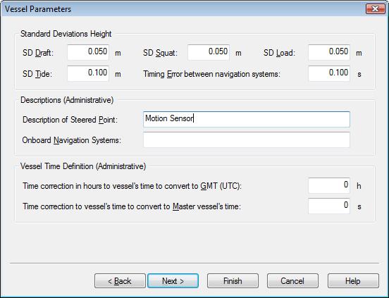
Enter a priori standard deviations for draft (default 0.05 m), squat (default 0.05 m), load (default 0.05 m) and tide, including spatial and temporal prediction to the vessel position as well as tide file uncertainties (default 0.10 m).
Info
Be aware that the standard deviation values should reflect that for example no draft or load values are known or that no squat model or tide height will be used.
In such cases, one should enter higher values for the SDs.
These SDs are only used in case a position system height is set to unreliable in a Computation Setup, otherwise the SD of the position system height observation is used. See the Height Aiding Driver Window (below) when online (or in Replay).
The vessel parameter page is only available when object type is vessel or survey vessel. The other fields on this page only serve administrative purposes and are not applicable to the computation of TPU values.
Variable Node
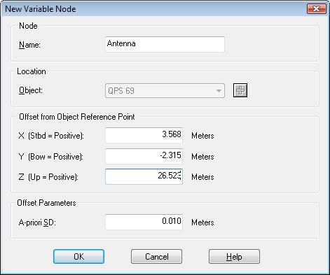
Enter a priori standard deviation for node offsets (default 0.01 m). This can be changed later in the Controller's Setup.
Position Navigation System
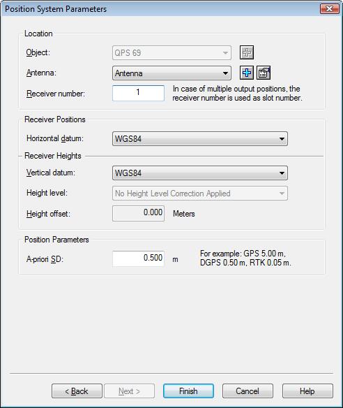
Enter a priori standard deviation for the latitude and longitude observations(default 0.5 m). The height observation will get an a priori standard deviation that is by default twice this value.
Info
This SD value is very important, since it is probably the most important contribution to the TPU values of an echosounder transducer node.
Make sure that its value reflects the type of positioning that is being used.
SD value can be changed later during an online or replay session in the Controller’s Computation Setup.
Gyro Compass
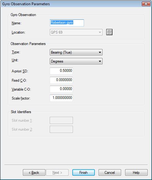
Enter a priori standard deviation for gyro heading(default 0.5°). The accuracy of a gyro is often given as a function of latitude, i.e. secant(latitude)=1/cosine(latitude).
A typical marine gyro compass relies on the latitude and the speed of the vessel, so the SD should reflect whether these switch settings are updated or not.
Fibre optic gyros and ring laser gyros can be an order of magnitude more accurate than traditional mechanical gyro compasses.
Pitch Roll Heave Sensor
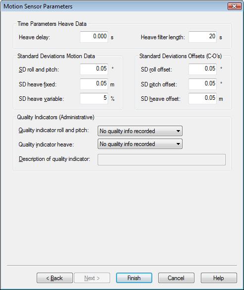
Enter a priori standard deviations for roll and pitch observations(default 0.05°). Heave observation, fixed part (default 0.05 m) and variable part(default 5%). Also a priori standard deviations for the alignment corrections or offsets (C-O’s) that have been defined on the previous page, i.e. roll offset(default 0.05°), pitch offset (default 0.05°) and heave offset (default 0.05 m). The accuracy of a heave observation is often expressed as e.g. “5 cm or 5%, whichever is highest”. The variable part will be higher if the swell is more than 1 m.
Info
The SD values for the offsets (C-O’s) should reflect the accuracy with which the alignment corrections have been determined.
Be aware that if no alignment checks have been done, i.e. offsets are left 0, one would expect even higher SD values that should be an indication of the possible uncertainties that can be made.
The fields for the quality indicators (QI) are only for administrative purposes.
Singlebeam Echosounder
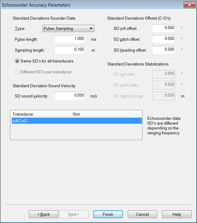
Enter a priori standard deviations for the echosounder observations as either pulse length and range sampling length (defaults 1 ms and 0.1 m) or pulse length and range sampling frequency(defaults 1 ms and 7.42 kHz). Range sampling length is determined by sound velocity as rs=c/2f , where f is the range sampling frequency. The type of SD for the echosounder data best corresponds with the type of accuracy values that the echosounder manufacturer has provided. The angle-range type of SD is only applicable for multibeam echosounders. Remember that different echosounder transducers will have different observation SDs, depending on the ranging frequency.
Enter also a priori SDs for the sound velocity from the echosounder unit(default 0.05 m/s), the alignment offsets (C-O’s) that have been defined on the previous page, i.e. roll offset(default 0.05°), pitch offset(default 0.05°) and heading (yaw) offset(default 0.5°). And the echosounder stabilization options if defined on the previous page, i.e. roll stabilization(default 0.05°), pitch stabilization(default 0.05°) and heave compensation(default 0.05 m).
Info
The beam opening angle defined on the transducer page is also very important for the TPU calculations.
Info
The SD values for the offsets (C-O’s) should reflect the accuracy with which the alignment corrections have been determined.
Be aware that if no calibration has been done, one would expect even higher SD values.
Multibeam Echosounder
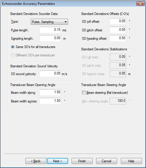
Enter a priori standard deviations for the MBE observations as either pulse length and range sampling length(defaults 0.15 ms and 0.05 m) or pulse length and range sampling frequency(defaults 0.15 ms and 14.85 kHz) or angle and range uncertainties(defaults 0.05° and 0.05 m). Range sampling length is determined by sound velocity as rs=c/2f, where f is the range sampling frequency. The type of SD for the echosounder data best corresponds with the type of accuracy values that the MBE manufacturer has provided. Only one transducer is supported.
Enter also a priori SDs for the sound velocity from the echosounder unit(default 0.05 m/s). For the alignment offsets (C-O’s) that have been defined on the previous page, i.e. roll offset(default 0.05°), pitch offset(default 0.05°) and heading (yaw) offset(default 0.5°). And the echosounder stabilization options if defined on the previous page, i.e. roll stabilization(default 0.05°), pitch stabilization(default 0.05°) and heave compensation (default 0.05 m).
Finally, enter the beam opening angles in along and across direction(default 1.5° and 1.5°) and select whether beam steering is applied or not(default no). For flat transducers, beam steering occurs for all the beams. Enter the minimum steering angle(0° for a completely flat transducer). The beam opening angles and beam steering angle are only used for the TPU calculations, but they are very important in order to get realistic uncertainty values.
Info
The beam opening angles have a large influence on the horizontal TPU value. It might be that the footprint detection is more accurate angular wise than the beam opening angle and in that case a smaller opening angle might be more appropriate.
Note that there is other software used in the hydrographic industry that does not even take the beam opening angle into account.
Info
The SD values for the offsets (C-O’s) should reflect the accuracy with which the alignment corrections have been determined.
Be aware that if no calibration has been done, one would expect even higher SD values.
USBL System
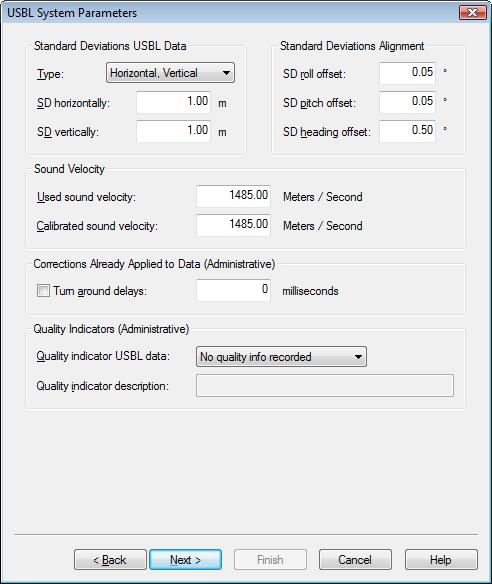
Enter a priori standard deviations for the USBL observations as either horizontal and vertical uncertainties (defaults 1 m and 1 m) or angle and range uncertainties (defaults 1° and 1 m). Also a priori standard deviations for the alignment corrections or offsets (C-O’s) that have been defined on the previous page, i.e. roll offset (default 0.05°), pitch offset (default 0.05°) and heading (yaw) offset (default 0.5°). The type of SD for the USBL observations best corresponds with the type of accuracy values that the USBL manufacturer has provided.
Info
The SD values for the offsets (C-O’s) should reflect the accuracy with which the alignment corrections have been determined. If available, enter the 1s values (68% confidence level) from the USBL calibration utility.
Be aware that if no calibration has been done, i.e. offsets are left as they were, one would expect even higher SD values that should be an indication of the possible uncertainties that can be made.
The ratio between the two sound velocity values is used as a scale factor (‘calibrated velocity’/’used velocity’) for the USBL observations. The other fields are only for administrative purposes.
System Observation Parameters

Enter a priori standard deviations for all the observations of surface navigation systems and underwater sensors, especially for ROV depth observations(default 0.1 m) and sound velocity observations (default 0.05 m/s).
An ROV depth observation SD value is used in the Height Aiding driver to compute a realtime standard deviation for the height observation if the ROV depth is used for the object’s height.
The sound velocity SD value is used in the MultiBeamer module if the sound velocity observation is used for beam angle correction with a multibeam system.
Online
Sound Velocity Profile
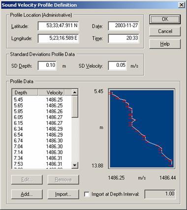
Enter a priori standard deviations for the depths(default 0.1 m) and velocities(default 0.5 m/s) in a profile, these values need to be entered in the database setup for the sound velocity profile.
This SD value will also be used for any sound velocity profile that is imported online in the Controller.
Controller Computation Setup
There are several a priori standard deviation values that can be changed in the Controller online or during a Replay session. These are either SDs that are used by the Adjustment module to get the covariance matrices for all the nodes in a computation, or SD’s that are used by the Position Filter module to compute the (Kalman) filter gain.
Initially, the a priori SD values for the Computation Setup are copied from the corresponding database setup records. However, with the present QINSy version, there is no feedback from the computation settings to the database setup records, nor are computation SD values changed when database setup record SD values are changed afterwards. A priori SDs can be changed for the following observation types: GPS pseudo-ranges, differential corrections, height aiding observations, positions, ranges, (vertical) angles, USBL observations and manual laybacks.
As mentioned before the SD values for the positioning system are very important. They can be entered in the Computation Setup in different ways.
When Accurate is used for the positioning system, there are three different choices: System Driver, Computation Setup or Database Setup for position SD and height SD. The position a priori SD is used for the XY positions, the height a priori SD is used for the Z position.

If System Driver is chosen the SD value is used from for example the GST string from the positioning system.
Because this is a calculated SD value instead of a predefined one, it will be more reliable. If the SD string is missing, or the SD values in it are 0 or corrupt, the a priori SD values entered in the Computation Setup will be used.
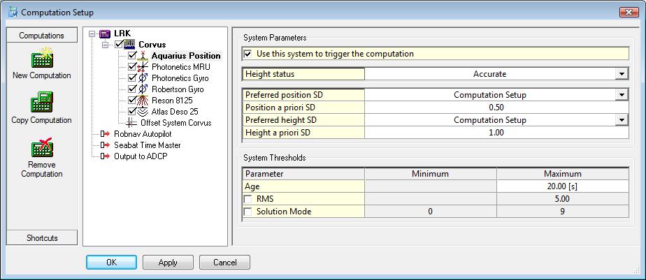
If Computation Setup is chosen, the values entered in the Computation Setup will be used.
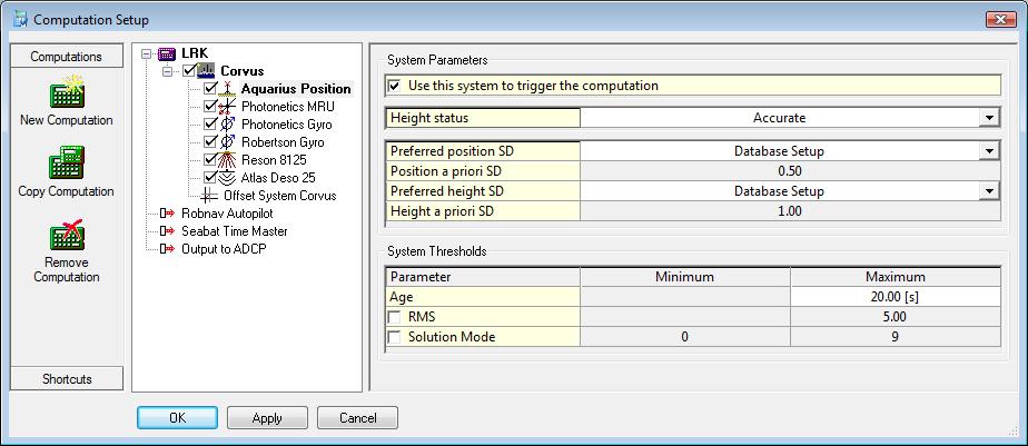
If Database Setup is chosen, the values entered in the Database Setup will be used. The value for Height SD will be twice as large as for position SD.
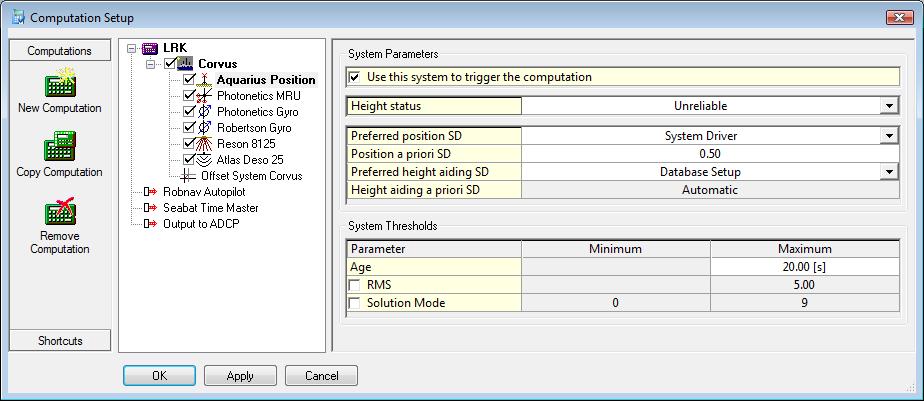
If the height status for the positioning system is set to Unreliable, the same three options for position SD as above are available. However for the Height aiding SD, there are only the options Database Setup or Computation Setup.
Info
It is recommended to set the SD height aiding observations to Database Setup, when the Height status is unreliable. Then the real-time SD as computed by the Height Aiding driver is used.
This SD is computed using all uncertainty sources that contribute to the height uncertainty. For a vessel object, this SD will usually vary with the heave amplitude (swell).
The Position Filter module will add the contributions of the Kalman filter and a time lag uncertainty (including the speed along-track component). The time lag uncertainty consists of an absolute time offset and an relative time offset between the positioning system and the echosounder systems. By default, the absolute time offset is 5 ms with a PPS system connected and 10 times as much (50 ms) when no PPS system is defined (PositionFilter registry key “PPS TimingError TPE”). The default relative time offset is 5 ms which can be entered as "Timing uncertainty between navigation systems" for the vessel parameters in the database setup.
Controller Echosounder Settings
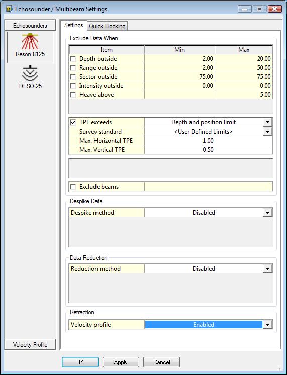
TPU values can be used as blocking parameters. Three options are available to exclude echosounder data, when (1) the vertical TPU exceeds the depth limit, (2) the horizontal TPU exceeds the position limit, or (3) the vertical TPU exceeds the depth limit or the horizontal TPU exceeds the position limit. The limits are obtained from two predefined survey standards, the IHO S-44 or the IMCA Guidelines. The actual limit values depend on the observed depths. It's also possible to choose User Defined Limits and enter the Maximum horizontal and vertical TPU value.
Height Aiding Driver Window
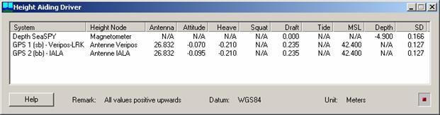
The Height Aiding driver computes a real-time standard deviation for each height aiding observation, using all uncertainty sources that contribute to the height uncertainty, i.e. dynamic draft (draft, load, squat), water level (tide gauge observation, tide file value, spatial/temporal prediction), depth observation, heave observation (fixed and variable components), induced heave (antenna offsets, pitch and roll observations), and MSL (depending on the geoid model; between 0.005 m and 0.2 m). For a vessel object, the height uncertainty will usually vary with the heave amplitude (swell).
The computed SD value is displayed in the last column in the Height Aiding driver window. This SD value will be used by the Adjustment module when the SD for a height aiding observation in the computation settings is 0.
Node QC Display
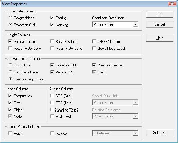
The TPU values for the echosounder transducer (and for all other nodes) can be displayed in a Node QC display by selecting the ‘Horizontal TPU’ and ‘Vertical TPU options’ under the ‘Position-Height Uncertainties ’ in the ‘View Properties’.
The TPU values are obtained from the full covariance matrix as computed by the Adjustment and PositionFilter modules. Both the horizontal value and the vertical value are scaled to 95% confidence levels.
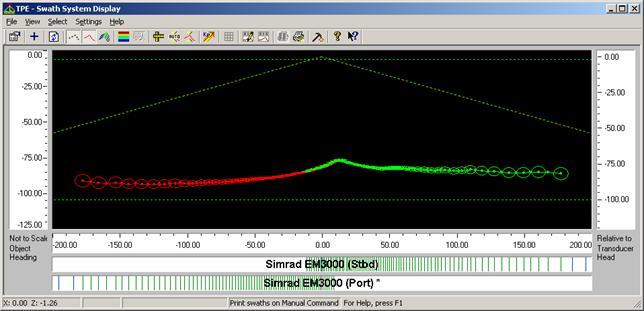
Swath System Display
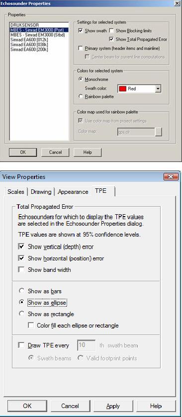
The TPU values for the echosounder footprints are computed by the MultiBeamer module. They can be displayed in a Swath System display by selecting the ‘Show Total Propagated Uncertaintie’ option in the ‘Echosounder Options’. The way in which the TPU values are displayed can be defined on the ‘TPU’ tab of the ‘View Properties’ dialog.
TPU values can be displayed for every Nth swath beam, or every Nth valid footprint point. The first option will always show the same beams (if they are valid and drawn). The latter option counts the beams that are valid and drawn.
Processing - Validator
When the reduced QPD storage was used then all data points that exceeded the TPU settings will not be stored in the file.
When the QPD file was saved as not reduced then all the data points are available. The data points that exceeded the TPU settings during the survey have been flagged. The flagging can be for exceeding the XY setting or exceeding the Z setting.
In the Validator there are filter options that can remove the TPU blocked data. The filters can be set under the Clip on flag option.
Processing - Qimera
See for more info this page:
References
[1] “IHO Standards for Hydrographic Surveys”, S-44 Edition 6.0.0, International Hydrographic Organization, Monaco, 2020.
[2] “Guidelines for the Use of MBES for Offshore Surveys”, IMCA S 003, International Marine Contractors Association, London, UK, 2001.
[3] Rob Hare, “Depth and Position Error Budget for Multibeam Echosounding”, International Hydrographic Review, Monaco, LXXII(2), September 1995.
[4] Rob Hare, “Error Budget Analysis for US Naval Oceanographic Office (NAVOCEANO) Hydrographic Survey Systems”, HSRC, University of Southern Mississippi, Hattiesburg, USA, September 2001.
[5] Erik Hammerstad, “Multibeam Echo Sounder Accuracy”, EM Technical Note, 16 March, 2000.