
How-to Timing in Qinsy
Timing of sensor data is an essential part of any hydrographic data acquisition system.
Regardless of hydrographic survey philosophy or software development principles, it all starts with the absolute timestamp in a common reference frame of the data provided by the sensors used during the survey acquisition phase.
Discussions on timing are often held in the context of multibeam echosounder data acquisition or deep water construction, where the effects of timing errors become apparent with a vengeance.
On this page:
Philosophy
QPS’ philosophy on hydrographic surveying is based on the principle of “doing it right the first time around” and to have the final product calculated on-the-fly during survey acquisition. This philosophy forced a deep hard look on data time stamping early on in the blueprint developments of Qinsy back in 1994. Exhaustive tests with boring user interface-less applications were performed for several months. The sole purpose was to ensure the fundaments of the hydrographic data acquisition package Qinsy would be solid enough to build on.
This timing building block became the core component of Qinsy and one would think that with a time stamping mechanism proven to be inside 1 millisecond, discussions around timing would be something of the past. Unfortunately, over time it became clear that this was a utopian wish. Before elaborating on this some more; first a little technical background on the Qinsy time stamping mechanism.
Timing in Qinsy
The Qinsy time stamping mechanism is based on the 1 pulse per second (Time Synchronization) signal transmitted from GNSS receivers. This signal is an electronic pulse lasting a specified amount of milliseconds. The corresponding absolute UTC time is sent over a serial port (or other communication means) from the GNSS receiver.
This sounds relatively straight forward. However, various GNSS manufacturers provide this Time Synchronization timing data in various forms. Time stamps are sent before or after the pulse. The time reference can be the rising or falling flank of the pulse. Some receivers have time offsets between time message and pulse. Most GNSS receiver documentation does not provide these details, adding difficulty to the quest for accurate time stamping.
The electronic pulse can be caught in a computer through a special device that converts the electronic pulse to a dedicated message that can be read via the computer I/O port. QPS manufactures such a device. This relatively cheap device is called the QPS TTL Time Synchronization Connector.
The actual time message, which contains the absolute UTC time value, can be read from a computer I/O port just like any other data read from the GPS receiver. Combining the electronic pulse and the corresponding time value in Qinsy, an absolute GPS-based UTC clock is generated. This clock is based on a special high resolution timer which gives a much better resolution than the standard internal Windows™ timer that is limited to a 10 to 15 millisecond resolution. This high resolution timer is the common time reference frame for all interfaced sensors providing data to Qinsy. The accuracy of this internal 1 Time Synchronization UTC clock has been proven to be better than 0.5 milliseconds.
It is vital that the 1 Time Synchronization signal is handled by a computer serial communications port with a dedicated hardware IRQ (interrupt request) line. In practice this means a serial communications port on the computer system (e.g. COM1) instead of a channel of a multi-comms board, or worse, a serial to USB converter.
All data received through the computer I/O ports is tagged with a UTC timestamp from the 1 Time Synchronization UTC clock. Keeping all received data in FIFO (first-in, first-out) buffers allows Qinsy to pick all received data for a particular time slice. The accuracy of time tagging serial data depends highly on the hardware and accompanied operating system drivers and how they use the internal PC IRQ lines. Usually it takes some time for the operating system to respond to the serial character reception event. This is caused by the time slice which is 10 milliseconds on a single CPU computer. This introduces a potential latency between 0 and 10 milliseconds caused by the time difference between the actual event and the handling of the event the next time slice. For time critical I/O drivers QPS has developed high-precision drivers using a different kind of serial interface approach to avoid this variable latency.
Having eliminated this source of latency only one remains: the latency of the I/O hardware. Tests with PC serial ports and different multi-comms boards demonstrated different latencies ranging from 1 to 35 milliseconds. These tests are described later on in this document.
As stated before, this principle provided a timing accuracy of 1 millisecond. This is the best result that can be obtained using the Windows™ operating system on off-the-shelf computer hardware. Analysis of countless volumes of online recorded data proved that this is more than enough for the purpose for which the data was collected. Combining rational survey principles with sensor accuracy the quest for 1 millisecond is becoming a hype in the industry taking the focus off of standard hydrographic survey practice. Hardware time stamping solutions, providing time stamping with an accuracy of 1 millisecond, are commercially off-the-shelf available and have been in operation in the industry for close to 2 decades. Obviously there is more to it than time stamping to 1 millisecond; otherwise the industry wouldn’t be buzzing with discussions on timing.
Hardware Latency
QPS has performed large numbers of extensive tests to investigate the internal latency of various multi-comms boards available on the market and used in the industry (COTS). By comparing time stamps between hardware time stamped data and the same data time stamped through the computer multi-comms board we investigated if the timing principle used in Qinsy can be implemented in real life. The operating system handles the I/O through drivers provided by the multi-comms board manufacturers. If the operating system handles the I/O from these multicomms boards, through their drivers, with large or variable latencies the timing principle remains academic.
The following table shows our findings. It shows the internal latencies, in milliseconds of multi-comms boards we tested. Detailed reports can be provided upon request. Please contact QPS for the complete report.
All manufacturers have the option to allow the size of the Rx FIFO buffer to be controlled of each port. The effects of these settings are clearly visible in the table above. All tests are identical and were done at different baud rate settings and at different Rx FIFO settings. The results are evident.
| Manufacturer | 9600 bps | 19200 bps | 38400 bps | 57600 bps |
|---|---|---|---|---|
| PERLE - UltraPort8i (Rx FIFO = 56) | 34 | 17 | 9 | 6 |
| PERLE - UltraPort8i (Rx FIFO = 8) | 9 | 4 | 2 | 2 |
| MOXA -- NPort 5410 (Rx FIFO = Enabled) | 45 | 28 | 20 | 17 |
| MOXA -- NPort 5410 (Rx FIFO = Disabled) | 12 | 12 | 11 | 11 |
| MOXA - CP-168U V2 (Rx FIFO = 120) | 34 | 17 | 9 | 6 |
| MOXA - CP-168U V2 (Rx FIFO = 1) | 1 | 1 | 0 | 0 |
| DIGI Neo Universal(Rx FIFO = 56) | 34 | 17 | 9 | 6 |
| DIGI Neo Universal(Rx FIFO = Disabled) | 1 | 1 | 0 | 0 |
| DIGI AccelePort Xem(Rx FIFO = Default) | 11 | 12 | 12 | 11 |
| DIGI AccelePort Xem(Rx FIFO = Disabled) | 11 | 12 | 12 | 11 |
| ASUS P5B-800 COM1(Rx FIFO = 14) | 15 | 8 | 4 | 3 |
| ASUS P5B-800 COM1(Rx FIFO = Disabled) | 1 | 1 | 1 | 0 |
| ASUS P5B-800 COM2(Rx FIFO = 14) | 15 | 8 | 4 | 3 |
| ASUS P5B-800 COM2(Rx FIFO = Disabled) | 1 | 1 | 0 | 0 |
Table 1 Internal latencies of multi-comms boards in milliseconds
Conclusion:
The measured latencies from the DIGI AccelePort Xem and MOXA - Nport 5410 are variable; the number shown is an average of all measurements.
Disable the Rx FIFO settings or specify the minimal value possible for the sensors, e.g. an MRU, with timing sensitive data. This is not the default configuration of the multi-comms cards when they are built in the first time!!
Make sure communications are done at the highest possible baud rate. The dramatic drop in I/O latency just by increasing the baud rate should force every one to re-check all on-line interfacing.
The CPU load increase due to the lowering of the Rx FIFO buffer is marginal. Tests concluded that the increase in CPU load averages at 8% increase if all ports have lowered, or disabled FIFO, buffers.
No increase in CPU load could be measured if only the ports receiving timing sensitive data have lowered, or disabled, Rx FIFO buffers.
Time Synchronization Time Stamping Tests
This section describes the tests mentioned in the previous chapter in more (technical) detail.
In order to properly test timing performed in Qinsy, a device with a higher accuracy than the elusive 1 millisecond was required. This was achieved by developing the QPS time stamping tester box.
Its sole purpose is to verify the Qinsy serial driver time stamping accuracies in an office test environment.
The QPS time stamping tester box can be configured to output serial messages in different formats at different baud rates. Output of the serial messages is synchronized to GPS time by means of Time Synchronization.
Supported baud rates are:
- 1200 bps
- 9600 bps
- 19200 bps
- 38400 bps
- 57600 bps
Other RS232 parameters used were: 1 start bit, 1 stop bit, no parity, 8 data bits.
Supported formats are:
- NMEA GPGGA
- NMEA HEHDT
- EM1000 Attitude
- TSS1
- Octans HEHDT, PHTRH, PHINF
Serial messages are output by the tester at a frequency of 25 messages per second.
Internal Working
The tester only works in combination with a GPS receiver that delivers a valid TTL Time Synchronization signal, active on the rising flank. The Time Synchronization signal of the GPS is connected to the tester box.
The tester contains an 8 bits microprocessor board that continuously monitors the Time Synchronization signal. If the flank of the Time Synchronization signal rises, the microprocessor resets an internal 25 Hz clock. Every time the clock increments the microprocessor sends a serial message. As the clock is synchronized to the Time Synchronization signal, the output pace of the messages is also synchronized to the Time Synchronization signal.
At 25 Hz, the transmission takes place every time the GPS clock reads: xx.000, xx.040, xx.080, xx.120, etc. (where xx represents a whole second).
Each time reading (at 25 Hz) is formatted into the output message as an observation. The program receiving the serial output message from the tester can decode at what time the message was transmitted by decoding the observation. Comparing the observation value formatted in the output message and the physical timestamp the output message is received in the acquisition computer is the latency of the serial I/O port.
Usage In Qinsy
This is done in Qinsy by defining a database with interfacing to a Time Synchronization system and the input of the QPS time stamping tester box.
Qinsy is brought on-line and the data is recorded. The received data is time stamped with Time Synchronization as is done with all sensor drivers in Qinsy. In this case the observation in the output message of the tester box, contains the 100% correct time stamp belonging to the data.
In the Raw Data Inspection tool of Qinsy a comparison can be made between the observation value (true time stamp) and the time stamp given to the data by the Qinsy Time Synchronization time stamping mechanism. If there were no latency, these values would be identical. Any difference between the two is the latency of the serial I/O port.
Tester Performance Validation
In order to verify the accuracy of the tester the following procedure was carried out:
- Set up the tester in combination with a GPS receiver
- Interface output of tester serial TX wire and Time Synchronization pulse wire to a dual channel oscilloscope
- The oscilloscope proved that the time difference between the rising flank of the Time Synchronization signal and the start of the transmission of the serial data was less than 1 millisecond
Sensor Output
The Achilles’ heel of accurate timing is the time discrepancy between the moment a sensor performs its measurements and the time the sensor transmits its results as computer readable data on an I/O port, better known as latency. Any latency between physical sensor measurement and availability of these measurements on the sensor I/O port will result in timing error effects. Not even time stamping to the nearest nanosecond will overcome this fact.
Some sensors provide their latency as part of the output message. Unfortunately these sensors are few and far between. And if one does have the luxury to be working with such a sensor, what is the accuracy of its internal latency measurement?
With sensors that do not provide a measured latency the potential inaccuracy only increases. Sensor manuals sometimes state values for latencies, but the latencies may vary with the chosen output rate, message type and selected interface protocol. If the manuals do not provide any insight on the potential latency of the sensor one is left to the technical support centers of the manufacturers.
With sensors that provide their data through LAN interfaces, instead of the common RS-232 interface, time stamping the data upon receipt in the computer is far too inaccurate to provide survey grade quality. Network delays are unpredictable and variable. These delays are also influenced by any activity on the network. Most current multibeam echo sounders provide their data through LAN. With the huge amounts of data it is only logical as LAN interfaces can handle much larger volumes compared to RS-232 serial interfaces. Forced to solve the timing problems accompanying LAN data transfer, these sensors have the capability to interface to the 1 pulse per second (Time Synchronization) and UTC time message, so data is internally time stamped to the UTC time frame.
Practical Responsibilities
This development is a big step forward. The sensor manufacturer is the only one who has the knowledge on the internal workings of the sensor. It shouldn’t be any other way. Who else is better equipped to time tag the data than the manufacturer of the sensor? Now the sensor can provide the measurements with the proper UTC time stamp through the 1 pulse per second (Time Synchronization) from the GNSS receiver. In actual fact this development is nothing new.
With the rise of the GNSS receivers in the industry the essence of this solution could be verified quite simply. A common time frame was one of the necessities of global satellite positioning. As a result the GNSS receivers provided their data time stamped to UTC time. It wasn’t difficult to measure the increase of internal sensor latency when it switched from position calculation with 5 satellites to 10 satellites or from stand-alone GPS to RTK positioning.
But all of that did not matter, providing the data acquisition system faced up to its responsibilities. The data from a sensor can be received 5 seconds late in the data acquisition system. As long as the data is accompanied by the proper UTC time stamp it can be placed in its correct perspective. The UTC driven sensor ring buffer principle in Qinsy takes care of the correct placement of all sensor data in the UTC time frame. The ring buffer also takes care of the correct interpolation of sensor data for the moment of the actual ping, fix, etc. So by no means is the timing issue a responsibility solely for the sensor
manufacturers. There is a well-defined line where one responsibility ends and where the other begins. The burden of timing responsibility is shared by the sensor manufacturers and the builders of data acquisition systems.
Timing Error Quantification
The discussion on timing issues is mostly held on theoretical levels. At these levels the purpose of the need for extreme accuracy is lost. The following graphs show the effect of timing errors in the measured roll on a multibeam survey configuration, consisting of a GNSS receiver, multibeam echo sounder, gyro and motion sensor.
We can assume the GNSS receiver and multibeam echo sounder to be perfectly time stamped. The GNSS receiver will provide UTC time stamped data. The multibeam echo sounder will be interfaced to the 1 pulse per second (Time Synchronization) and also provide UTC time stamped data.
The graphs show the error in measured depth at 5° intervals from nadir to 75° off nadir. The actual depth is 20 m.
If we take a roll period of 5 seconds with a 3° amplitude, the maximum roll error due to a timing error of 5 milliseconds will be 0.012°. This error quantifies to the following errors in seafloor depth:
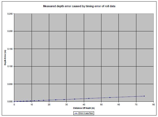
Figure 1 Errors in water depth measurement due to roll timing errors
Maximum depth error at 75° off nadir is 1.6 cm. To quantify some more: at 20 m depth the horizontal ensonified area (@ 0.5° opening angle) is 5.05 m (on a flat seafloor).
The IHO specifications for hydrographic survey accuracies are described in publications:
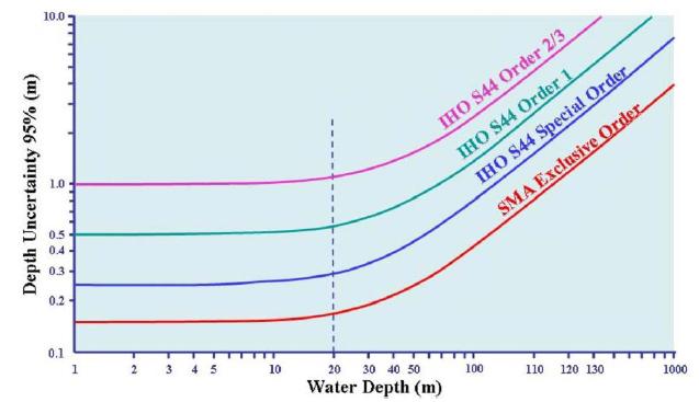
Figure 2 IHO S-44 publication
Similar tests can be performed on all other types of system drivers. The effect of timing errors on the various types of sensors also needs to be correlated with the accuracy and resolution of the data received from these sensors.
A positioning sensor sending out an NMEA GGA message with only 4 decimals in the latitude and longitude observations does not qualify for a millisecond time stamp accuracy requirement.
Taking all of this into account QPS has determined that mostly motion reference unit systems are timing critical and require the millisecond timing. Multibeam echo sounders are expected in this category, but only a few older types still have serial interfaces and no interfacing to Time Synchronization.
All current systems are interfaced through LAN and internally time stamped by Time Synchronization.
If for the motion reference units the specially high-precision drivers are selected the 1 millisecond time stamp accuracy can be realized. The standard TSS format is one of these drivers.
As all motion reference units can output this format, we advise to use this one.
The following table will illustrate this in a more practical way:
| Sensors internally interfaced to Time Synchronization that provide UTC time stamp in the output message * | Not timing critical |
| All GNSS sensors with time stamped messages * | Not timing critical |
| USBL sensors ** | Not timing critical |
| LAN interfaced sensors *** | Not timing critical |
| Motion reference units | Timing critical |
| Heading sensors | Timing critical |
* Data from sensor is provided with UTC time stamp and as such can always be properly referenced.
** Inaccuracy of data from sensor is of a much larger magnitude ever recovered by millisecond timing.
*** No LAN interface can be properly time stamped upon reception. Data needs to be synchronized to Time Synchronization and time stamp provided in the data message.
Finding and applying latency
Please refer to the following document, where the 'Wobble Tool' is used to determine latency: How-to Use the Wobble Analysis Tool.
Conclusions
Problems with time tagging of sensor data have always been the whipping boy in the hydrographic industry. This problem must be seen as a shared problem between sensor manufacturers and data acquisition system manufacturers.
The former is responsible for the internal sensor latencies; the latter is responsible for proper handling of data.
As long as this is not seen as a shared problem, bringing electronic timing devices in to play that will time tag sensor data upon reception with extreme accuracies may end up in flogging a dead horse.
As can be seen from the table, time stamping accuracies of 1 millisecond can easily be achieved with off-the-shelf multi-comms boards.
For timing critical sensors QPS provides the following guidelines:
- Use highest possible baud rates
- Use the Qinsy driver specifically developed for this purpose (e.g.: TSS)
- Disable FIFO or use lowest possible settings
- The following multi-comms boards are tested and accepted by QPS for timing critical survey operations:
- DIGI Neo Universal
- MOXA - CP-168U V2
- PERLE -UltraPort8i
See "Serial IO Cards" for a complete overview.