
How-to Quality Management System
When the Quality Management System (QMS) is activated, information relating to the survey project is written to an XML file.
This happens during the various stages of a survey, either automatically or at user intervention.
The resulting file can be used for reviewing the survey project.
On this page:
QMS does not automatically log information to an XML - you must enable the function from the Console.
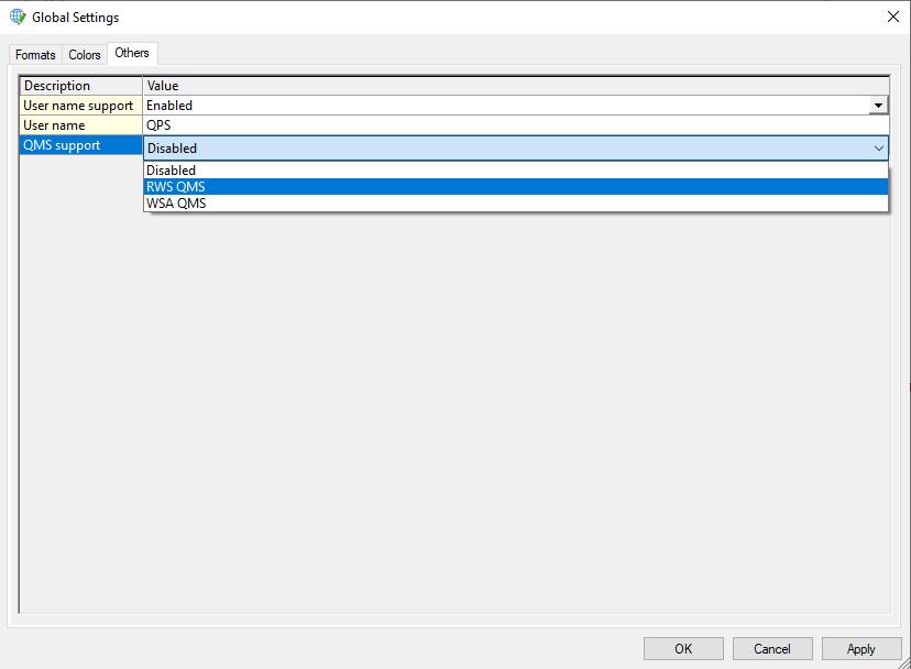
To enable QMS Support in Qinsy go to “Settings” on the menu bar and select “Global”. Select the tab “Others”.
From the pull-down menu select one of the available QMS support formats. Press “Apply” and then “OK” to save and exit the Global Settings.
The Console layout is then modified.
The difference between the selectable QMS systems is the type of information written to the XML file(s). Both companies have their own QMS system.
The available QMS options are:
- 43507831 Exports information to XML files needed for the RWS QMS system
- 43507831 Exports information to XML files needed for the WSA QMS system
RWS QMS
The applications in Qinsy that have RWS QMS support are listed below:
Acquired data is stored in three different categories; each is stored separately.
These categories are:
- Maintenance
- Acquisition
- Validation and processing
Where the quality management data is stored depends on the type of operation. Some applications are used in more than one operation therefore they export to multiple categories.
Alert Display
In the Alert Display, four observations generate a QMS output to the XML file:
Pitch outside limit
Specify upper and lower limit for pitch.
Roll outside limit
Specify upper and lower limit for roll.
Speed outside limit
Specify upper and lower limit for speed.
Linebearing deviation above limit
Specify a limit for difference between line bearing and vessel heading.
When an observation exceeds a limit an alert is fired. The QMS information sent to the XML file is:
- Name of the alert
- Start and end time of the alert
- Duration of the alert
- Upper and lower limit of the alert
- Recorded value to set of the alert
To enable the export to QMS from the Alert display go to “View” on the menu bar and select “Properties”, or select the “Properties” option from the toolbar.
Select “Export to QMS When Alert Fires (Only when recording)”.
Fired alerts are stored in the Acquisition XML.
Controller
The Controller has multiple exports to the categories Maintenance and Acquisition XML. All these exports are automatic.
Draft
The Draft value that is entered in the Computation Setup.
Draft is exported as soon as the Controller is started, along with date and time. When a new draft value is entered, the new value, date and time are exported.
This information is exported to the Maintenance XML.
Start and end time survey line
For each survey line recorded, the following information is exported:
- Line name
- Start date and time
- End date and time
- Name of grid file to where data is logged
This information is exported to the Acquisition XML each time a recording is started and stopped.
Sound Velocity profile
The sound velocity profile used is exported to the XML file. In case the option to use a sound velocity profile is disabled it will be exported to the XML file.
When a sound velocity profile is used, the following information will be exported:
- The time at which the sound velocity profile is updated
- File name of the profile (only when a file is imported)
- Easting and Northing of profile record
- Number of values in profile
- Minimum, maximum and mean speed
- Max. depth
Every time an adjustment is made to the sound velocity profile, or when a recording is started, the information is logged to the Acquisition XML.
Online Filters
The use of online filters is logged to the XML file. The following filters trigger an export:
- Blocking parameters
- Despike method
- Reduction method
Each time a new recording is started this information is logged to the Acquisition XML file.
DrvSercelAquariusUI.exe
The DrvSercelAquarius.exe driver decodes information from the Sercel Aquarius LRK receiver. When the Controller is started, the time, date and reference station identifier are logged to the XML file.
Whenever a new reference station is selected, time and date are logged in addition to the old and new reference station identifiers. This information is automatically logged to the Acquisition XML.
Establishment Fix
The Establishment Fix can be used for a position check. This calibration utility compares collected positions to a fixed location to calculate position accuracy.
The utility is started from the Options menu in the Controller. Results of the position check are logged to the Maintenance XML file.
The following items are logged:
- Start and end time of the calibration
- Number of positions that are used for the calibration
- Mean Easting, Northing and height
- Standard deviations for Easting, Northing and height
Gyro and height calibration
The Gyro Calibration is provided for the gyro and height calibration. This module is started from the Options menu in the Controller.
The results can be exported to QMS where they will be logged in the Maintenance XML.
Select the column of interest and select “Export To QMS”.
Tide Processor
When the Tide Processor is used all the defined tide stations are automatically logged in the Processing XML.
The tide stations are defined in the Tide Data Manager.
Validator
The Validator exports these items to the XML file:
Comparison between two survey lines (single beam only) or with a theoretical profile
As a check on current soundings, a comparison survey line can be sailed and loaded in the Validator together with a reference survey line.
A comparison can be made between two sailed lines or between a theoretical profile and a survey line.
To compare two lines open both lines in the Validator and select the option Compare from the Edit menu in the Validator.
To export the results to the XML file select “Export to QMS” and select to which category it must be exported. A choice can be made between Maintenance and Acquisition.
It is also possible to compare a sailed line to a theoretical profile. The theoretical profile is a survey line defined in the Survey Manager.
In this case the heights of the sections in the line are important:
- Create a survey line in the Survey Manager
- Instead of only entering Easting and Northing also specify the height of the specific line sections so that a profile is created.
- Go online with the Controller and set the created Theoretical Profile survey line as current survey line and record the depth to a QPD file (DTM file).
Offline filters and manual de-spiking
When QMS is enabled in Qinsy the filters used in the Validator are automatically logged in the Processing XML. For each filter the settings used are exported.
When de-spiking is done manually the following information is exported:
- Total number of observations
- Number of accepted observations
- Number of rejected observations
- Accepted percentage
- Rejected percentage
Go to “File” on the menu bar and select “Save” in order to log the manual de-spike information to the Processing XML.
Merging and merging method
When single beam data is merged to one QPD file (DTM file) the following information is automatically logged to the Processing XML:
- Method of merging
- The name of the newly created QPD file
- The QPD files which were used to merge and create a new file
WSA QMS
In the WSA QMS format all quality information is stored in one single XML file. This XML file is only created when a DTM file is stored when recording or replaying the data.
The WSA QMS XML contains the following list of information:
General
The XML file starts with a general header including information on project name, vessel name and Qinsy version.
Comment
The information stated in the comment part of the XML file is manually entered by the user. The location to enter this information can be found in the Controller - Settings - Session Setup - Storage - DTM file.
Select the DTM file format *.mbes - Binary WSV. This format is only available in case the WSA QMS option is enabeld in the project.
Entered information will be stored in the XML file, even when a different DTM file format is selected to store the data in.
Line
Information on the Sailed Line: start time, end time, start fix, end fix, duration, used survey line, current active template database, storage database, dtm file, sounding grid file, minimum KP, maximum KP, minimum Easting, minimum Northing, maximum Easting and the maximum Northing.
Geodesy
The geodesy parameters as entered in the template database.
Calibration check
Results of the last performed gyro calibration and position check within the project. These are started from the Controller.
In case of the positioning check the data is automatically written to the XML file.
In case of the gyro calibration use the available button in the user interface to write the data to the QMS XML file.
Positioning parameters
Information on the selected computation.
Sound velocity profile
Information on the available sound velocity profile in the database.
Echosounder settings
For each echosounder system the values for the selected echosounder settings are given.
The echosounder settings are set in the Controller.