
How-to Cable Catenary
A catenary is the curve that an idealized hanging chain or cable assumes under its own weight when supported only at its ends.
Page contents:
Cable Catenary support in Qinsy
For cable lay operations a Cable Catenary can be calculated.
The cable catenary can be calculated based on 4 different methods:
- USBL Layback - This driver will carry out the calculations of where the towed object is positioned.
- Departure Angle - The cable departure angle as measured from the rear of the vessel will be used for calculations.
- Tension - A device controlling the tension on the wire is used for calculations.
- Touchdown - Distance to the object to be positioned and water depth are used for the calculating the known touchdown position.
In addition to the catenary also the bottom tension, the minimum bend radius and the Flop Forward position are calculated.
The as laid position can be stored for reporting. The results can be displayed in the Navigation and the Profile Displays and also as numerical values in the Generic Display.
Note that these methods are only shown when the add-on Cable Lay is enabled on the dongle.
For advanced catenary functionality where material properties, multiple cables and current need to be taken in account, QINSy offers the integration with OrcaFlex from Orcina (https://www.orcina.com/SoftwareProducts/OrcaFlex/).
Glossary of Pipe-Laying Terms
| Anode | Soft metal fitted at regular intervals to cathodically protect pipe from decay. |
B/S Beadstall | First welding station on a lay barge. Normally the main reference point. |
| Counter Weight / Counteracts | Large weight placed on the inside of curves to hold the pipe. |
| CP Survey | Cathodic Protection Survey. |
| Cut to length | Calculation done to decide final length of pipe to build before a lay-down. |
| DMA | Dead Man Anchor. A heavy object fixed on shore or on the seabed to temporarily hold a mooring line. |
| Dope station | Area where field joints are coated in bitumen. |
| FJ | Field Joint |
| Flop / Forwards | The Flop Forward point is the point where the pipeline or cable would end if it were lowered from the barge and were placed flat on the sea floor. |
| FOF | Face Off Flange. |
| Layback | Distance from reference point to touch down. |
| Mattress | Where two pipelines cross over each other, the pipeline crossing has to be protected. |
| MIF | Mattress Installation Frame. |
| Mill Count | Calculation of length based on factory provided lengths of each joint. |
| Overbend | First curve as the pipe leaves the stinger. |
| PHI | Departure angle at stinger. |
| Pig Launcher / Catcher | Large unit at the end of pipe which contains Pigs which are pushed through the pipe pneumatically to clean or test them. |
| Pin Pile | Method of starting a lay using a pile instead of an anchor. |
| PLEM | Pipe Line End Manifold. |
| Pull | Forward movement of the barge for one or two joints (Double jointing). |
| Pup | Short piece of un-coated pipe. |
| Sagbend | Last curve as the pipe touches the seabed. |
| Sleepers | Areas of rock that act like railway sleepers for the pipe. |
| Snake Lay | Pipe route with regular curves to cope with later expansion. |
| Spool piece | Section of pipe made to measure to connect up pipes. |
| Stinger | Supporting frame for the pipe hinged onto the stern of the vessel. |
| Tee Piece | T junction / connection in pipe, could be a hot tap. |
TP Touch down Point | Point at which the pipe no longer moves on the seabed (Hard). |
UT | Ultrasonic Testing. |
General
In the user interface Session Setup for Bargetrack the method can be selected and the following parameters need to be set:
- Cable weight above water, cable weight below water, depth, angle.
- Laying with a stinger or a chute can be set and the nodes need to be selected.
- For the chute the center of the radius needs to be selected and the radius needs to be entered.
- The mainline needs to be a route and the catenary will be calculated.
Method cable departure angle
In this method the cable departure angle is measured with a system such as a mechanical arm, a sensor on the cable or a laser system such as the DAMS by Pliant.
The angles need to be interfaced as Miscellaneous sensors.
- The vertical angle goes from 8 degrees (almost horizontal) to 89 degrees (which is almost vertically down). They are always positive numbers.
- Horizontal angles are in vessel reference and are positive to port and negative to starboard. An angle of zero is astern
- The horizontal angle is added to or subtracted from the vessel's heading.
Method tension
With the tension method a measured tension is used as input and with that the catenary and touchdown will be calculated.
There is no correction for vertical angle so the touchdown is directly behind the vessel.
Method touchdown
The touchdown position is known for instance when an ROV monitors this point.
The node for the camera needs to be selected and the catenary will be calculated.
Method USBL
The aft distance comes from a USBL observation.
With this layback the touchdown will be calculated.
Data logging
The catenary information is always stored in two types of files: a text file with the information such as touchdown, tension, and a graphics file (*.QGF).
The QGF can be shown in the Navigation Display so that the past laytrack can be shown.
The name of the graphics file is always touchdown_track and is logged in the LineData folder.
The name of the text file is always touchdown_results with the date and is in the Logging folder.
Visualization
Navigation Display
In the Navigation Display the following information is automatically shown:
Touchdown position, barge node, departure point and flop forward point.
The bargetrack is by default not enabled so this needs to be activated under Line Planning.
To show the past laytrack the file touchdown_track needs to be selected.
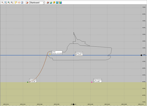
Profile Display
The Profile Display shows the catenary, the touchdown point, the chute node on board of the vessel, the barge node and the flop forward point including their KP values.
Flop Forward point
One point which is calculated and which is shown in the Navigation Display as a magenta-colored dot, is the Flop Forward point.
This is the point where the pipeline or cable would end if it were lowered from the barge and were placed flat on the sea floor.
This point is not a node, but it can be visualized in the Navigation Display, in the Profile Display and as alphanumerical data in the Generic Display.
The Flop Forward point is only shown when the vessel is in the vicinity of the bargetrack / selected KP line.
Generic Display
The Generic Display can show all cable lay and catenary values in a numerical way.
Other
Driver
Note that for cable lay operations there is also a so-called countdown driver available.
With the driver the exact point at which a cable needs to be cut can be calculated.
More information can be found in the Drivers Manual under: Countdown Length (Cable Counter - Distance To Go) - 23
Related documentation
- How-to Cable/Pipe Lay - Bargetrack
- Online Help of the Controller - Settings - Session Setup - Bargetrack